
Concept explainers
Videos
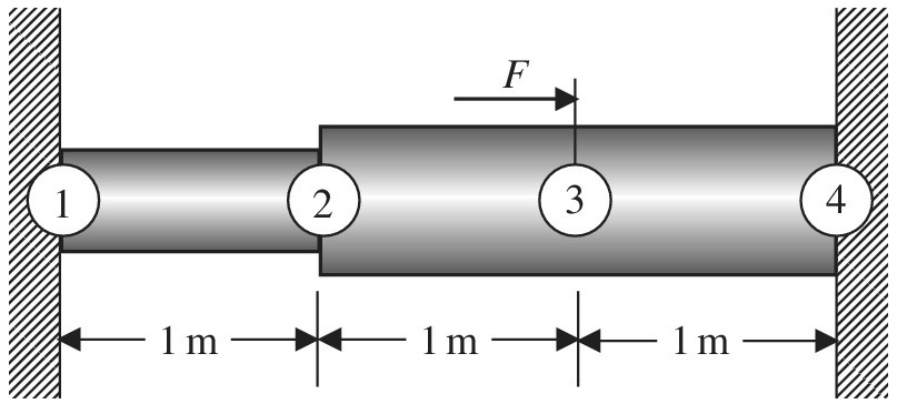
A stepped bar is clamped at both ends. A force of
a. Sketch the displacement field
b. Calculate the stress at a distance of 2.5 m from the left support.
Want to see the full answer?
Check out a sample textbook solution
Chapter 1 Solutions
Introduction To Finite Element Analysis And Design
Additional Engineering Textbook Solutions
Thinking Like an Engineer: An Active Learning Approach (3rd Edition)
Applied Fluid Mechanics (7th Edition)
Heating Ventilating and Air Conditioning: Analysis and Design
Manufacturing Engineering & Technology
Statics and Mechanics of Materials (5th Edition)
Fundamentals Of Thermodynamics


- A stepped shaft ABC consisting of two solid, circular segments is subjected to uniformly distributed torque t1acting aver segment 1 and concentrated torque t2applied at C, as shown in the figure. Segment 1 of the shaft has a diameter of d1= 57 mm and length of L1= 0.75 m; segment 2 has a diameter d2— 44 mm and length L2= 0.5 m. Torque intensity /,"= 3100 N . m/m and T2= 1100 N. m. (a) Find reaction torque TAat support A. (b) Find the internal torque T(x) at two locations: .x = L1/2 and at .x = L1+ L2/2. Show these internal torques on properly drawn free-body diagrams.arrow_forwardA bungee cord that behaves linearly elastically has an unstressed length L0= 760 mm and a stiffness k = 140 N/m. The cord is attached to two pegs, distance/? = 380 mm apart, and is pulled at its midpoint by a Force P = 80 N (see figure). (a) How much strain energy U is stored in the cord? (b) What is the displacement Scof the point where the load is applied? (c) Compare the strain energy (with the quantity PSC12. Note: The elongation of the cord is not small compared lo its original length.arrow_forwardIn the figure, copper AB copper with a diameter of 24 mm and BC steel bars with a diameter of 20 mm are rigidly connected to each other at point B. A force of 6 kN was applied to the rod at the B point and 12 kN at the C point. Since the modulus of elasticity of copper is 100 GPa and the modulus of elasticity of steel is 200 GPa, find the displacement of the C point.arrow_forward
- Suppose that the assembled stiffness matrix of question 1 (as shown below) is as follows: [K]=108×a-a0-aa+b-b0-bb where a=4.06 N/m and b=2.28 N/m. If the applied force at node 3 is P=210 KN, find the displacement of node 2 in mm?arrow_forwardFind the change in length between the points A and D on the bar given in the figure E= 4.10 5kN/cm2arrow_forwardFind the natural frequency (in Hertz) of the system illustrated in the following figure. Consider the length of the rigid bar as 2L and assume K1=4,659 N/m, K2=5,977 N/m, M=0.6 kg, L=0.5 m and g=9.81 m/s2.arrow_forward
- The dimensions are of the graph are d1 = 7 cm , L1 = 6 m , d2 = 4.2 cm , and L2 = 5 m with applied loads F1 = 130 kN and F2 = 60 kN . The modulus of elasticity is E = 80 GPa . Use the following steps to find the deflection at point D. Point B is halfway between points A and C. What is the reaction force at A? Let a positive reaction force be to the right.arrow_forwardSafe normal and non-slip of wooden beam material stresses are respectively σem = 10 MPa and τem = 0.8 MPa. The maximum q that a simple beam can carry is Find the distributed charge.arrow_forwardThe cylindrical AC aluminum and CB steel bars in the figure are combined and placed between two rigid plates at A and B, but there is a gap of A=0.1 mm between the B plate and the bars. The modulus of elasticity of aluminum is E-70 GPa and the cross-sectional area is A-400 mm², the modulus of elasticity of steel is Eç-210 GPa and the cross-sectional area is -200 mm³. the lengths of the bars are LAC-200 mm and L CB-600 mm. Since a load of P-30 kN is applied to point C What is the stress in the AC aluminum bar?arrow_forward
- The cylindrical AC aluminum and CB steel bars in the figure are combined and placed between two rigid plates at A and B, but there is a gap of A=0.1 mm between the B plate and the bars. The modulus of elasticity of aluminum is E-70 GPa and the cross-sectional area is A-400 mm², the modulus of elasticity of steel is Eç-210 GPa and the cross-sectional area is -200 mm³. the lengths of the bars are LAC-200 mm and L CB-600 mm. Since a load of P-30 kN is applied to point C What is the displacement of the bar AC?arrow_forwardfind the deflection under the load f in the following sketch using the following two approaches: a. Assume the bar is rigid ( EI don't matter) using the Principe of Stationary Potentiel Energy. b. Assume the bar is flexible (EI matter) using the rayleigh-ritz method. hint: you can assume a polynomial displacement field with two d.o.f. c. How do the answers from parts (a) and (b) compare if, in part (b), you also assume that ei = kl3? in this case, you should be able to write your displacement for part (b) again in terms of only f, k, and maybe l.arrow_forwardQuestion 1) In the beam whose loading condition is given in the figure, F force F= 79 kN, w1 distributed load w1= 44 kN/m, w2 distributed load w2= 55 kN/m, θ angle θ= 49° and L length L= 9 m given. According to this;Question 1-A) Find the support response in the y direction (By) at point B. (Enter your result without writing kN units.)Question 1-B) Find the support response in the y direction (Ay) at point A. (Enter your result without writing kN units.)Question 1-C) Find the support response in the x direction (Ax) at point A. (Enter your result without writing kN units.)arrow_forward
 Mechanics of Materials (MindTap Course List)Mechanical EngineeringISBN:9781337093347Author:Barry J. Goodno, James M. GerePublisher:Cengage Learning