
Engineering Electromagnetics
9th Edition
ISBN: 9780078028151
Author: Hayt, William H. (william Hart), Jr, BUCK, John A.
Publisher: Mcgraw-hill Education,
expand_more
expand_more
format_list_bulleted
Concept explainers
Videos
Textbook Question
Chapter 10, Problem 10.42P
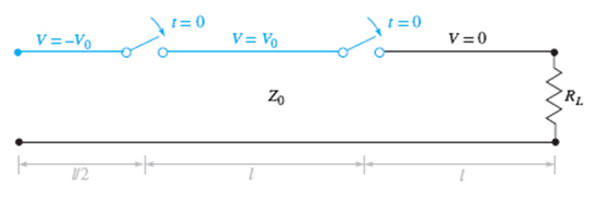
Figure 10.38 See Problem 10.42.
A simple frozen wave generator is shown in Figure 10.38. Both switches are closed simultaneously at t = 0. Construct an appropriate voltage reflection diagram for the case in which RL = Z0. Determine and plot the load resistor voltage as a function of time.
Expert Solution & Answer
Want to see the full answer?
Check out a sample textbook solution
Students have asked these similar questions
Consider a 10W power transmitter and a 30dB transmission antenna, the EIRP value will be: Select one or more than one:
a. The value of the EIRP is: 10000watt
b. The EIRP value is :50dBW
c. The EIRP value is: 200 Watt
d. The EIRP value is: 40dBw
4. Derive the equation to get the message from DSB-SC signal usinghomodyne receiver.
Q/What is the effect of the length of the transmission line on the Phasor measurement unit (PMU) performance ?
Chapter 10 Solutions
Engineering Electromagnetics
Ch. 10 - The parameters of a certain transmission line...Ch. 10 - A sinusoidal wave on a transmission line is...Ch. 10 - Prob. 10.3PCh. 10 - A sinusoidal voltage V0, frequency , and phase...Ch. 10 - Two voltage waves of equal amplitude V0 and radian...Ch. 10 - A 50 load is attached to a 50-m section of the...Ch. 10 - Prob. 10.7PCh. 10 - An absolute measure of power is the dBm scale, in...Ch. 10 - A 100-m transmission line is used to propagate a...Ch. 10 - Two lossless transmission lines having different...
Ch. 10 - Two voltage waves of equal amplitude V0, which...Ch. 10 - In a circuit in which a sinusoidal voltage source...Ch. 10 - The skin effect mechanism in transmission lines is...Ch. 10 - A lossless transmission line having characteristic...Ch. 10 - Figure 10.29 See Problem 10.15. For the...Ch. 10 - A 100 lossless transmission line is connected to a...Ch. 10 - Determine the average power absorbed by each...Ch. 10 - The line shown in Figure 10.31 is lossless. Find s...Ch. 10 - A lossless transmission line is 50 cm in length...Ch. 10 - (a) Determine s on the transmission line of Figure...Ch. 10 - Prob. 10.21PCh. 10 - Prob. 10.22PCh. 10 - The normalized load on a lossless transmission...Ch. 10 - Prob. 10.24PCh. 10 - Prob. 10.25PCh. 10 - A 75 lossless line is of length 1.2 . It is...Ch. 10 - Prob. 10.27PCh. 10 - The wavelength on a certain lossless line is 10...Ch. 10 - Prob. 10.29PCh. 10 - A two-wire line constructed of lossless wire of...Ch. 10 - In order to compare the relative sharpness of the...Ch. 10 - In Figure 10.17, let ZL=250 and Z0=50. Find the...Ch. 10 - In Figure 10.17, let ZL=100+j150 and Z0=100. Find...Ch. 10 - The lossless line shown in Figure 10.35 is...Ch. 10 - Prob. 10.35PCh. 10 - The two-wire lines shown in Figure 10.36 are all...Ch. 10 - Prob. 10.37PCh. 10 - Repeat Problem 10.37, with, Z0=50 and RL=Rg=25....Ch. 10 - In the transmission line of Figure 10.20, Z0=50,...Ch. 10 - In the charged line of Figure 10.25, the...Ch. 10 - In the transmission line of Figure 10.37, the...Ch. 10 - Figure 10.38 See Problem 10.42. A simple frozen...Ch. 10 - Figure 10.39 See Problem 10.43. In Figure 10.39,...
Knowledge Booster


Learn more about
Need a deep-dive on the concept behind this application? Look no further. Learn more about this topic, electrical-engineering and related others by exploring similar questions and additional content below.Similar questions
- Could you please go more in depth about how to create the ac equivalant model? thank youarrow_forwardA system has a forward power of 60 W, reflected power of 3 W, and transmission line loss of –3 dB. What will be the observed loss on the ground? A system has a forward power of 200 W and a reflected power of 15 W, what is the return loss?arrow_forwardWhat are (a) the values of the intercept points in the load line and (b) the slope of the load line given the circuit?arrow_forward
- Find the basic path loss for a communication link from Moon to Earth operating at 4000 MHz. The distance between Moon and Earth is 384000 km.arrow_forwardFind the median path loss using Hata model for d= 10 Km, hte = 50 m, hre = 5 m in a urban environment. If the base station transmitter at a carrier frequency of 900 MHZ. Need Handwritten with All Formulas Clearly Mentioning. Thank youarrow_forwardUse the external excitation method for part a.arrow_forward
- A sinusoidal voltage wave is propagating on a low loss transmission line. The voltage as a function of position appears as shown below. From this plot, the damping coefficient α=arrow_forwardA 5.0 × 2.0 mm2air-filled rectangular waveguide is to operate below85 GHz. Determine the number of TE and TM modes that can be transmitted in the waveguide. Subsequently, sketch the cross-sectional view of field line distributions for TE10, TE11, and TM11 modes.arrow_forwardAGILA satellite is located 36000 km above the earth’s surface. Assuming free space condition, what is the path loss in dB of the signal if the operating frequency is 3 GHz. (Use two decimal places for the final answer)arrow_forward
- With a neat diagram show the reflections occurring in a transmission line. Hence explain thec conceptsof Reflection co-efficient and VSWR associated with it.arrow_forwardWhen does Naive Gauss Elimination fail?arrow_forward"A transmission line with negligible attenuation has L = 0.15 uH/ft and C = 0.1 nF/ft and is typically operated at 100 MHz. What is the velocity of propagation (in 10^8 m/s) of the signal along this line? Enter only the numerical value. No need for the unit. Use four decimal places (if the answer is not an integer). For example, the calculated value is 3x10^8 m/s, then enter 3."arrow_forward
arrow_back_ios
SEE MORE QUESTIONS
arrow_forward_ios
Recommended textbooks for you
 Introductory Circuit Analysis (13th Edition)Electrical EngineeringISBN:9780133923605Author:Robert L. BoylestadPublisher:PEARSON
 Delmar's Standard Textbook Of ElectricityElectrical EngineeringISBN:9781337900348Author:Stephen L. HermanPublisher:Cengage Learning
 Programmable Logic ControllersElectrical EngineeringISBN:9780073373843Author:Frank D. PetruzellaPublisher:McGraw-Hill Education
 Fundamentals of Electric CircuitsElectrical EngineeringISBN:9780078028229Author:Charles K Alexander, Matthew SadikuPublisher:McGraw-Hill Education
 Electric Circuits. (11th Edition)Electrical EngineeringISBN:9780134746968Author:James W. Nilsson, Susan RiedelPublisher:PEARSON
 Engineering ElectromagneticsElectrical EngineeringISBN:9780078028151Author:Hayt, William H. (william Hart), Jr, BUCK, John A.Publisher:Mcgraw-hill Education,
Introductory Circuit Analysis (13th Edition)
Electrical Engineering
ISBN:9780133923605
Author:Robert L. Boylestad
Publisher:PEARSON
Delmar's Standard Textbook Of Electricity
Electrical Engineering
ISBN:9781337900348
Author:Stephen L. Herman
Publisher:Cengage Learning
Programmable Logic Controllers
Electrical Engineering
ISBN:9780073373843
Author:Frank D. Petruzella
Publisher:McGraw-Hill Education
Fundamentals of Electric Circuits
Electrical Engineering
ISBN:9780078028229
Author:Charles K Alexander, Matthew Sadiku
Publisher:McGraw-Hill Education
Electric Circuits. (11th Edition)
Electrical Engineering
ISBN:9780134746968
Author:James W. Nilsson, Susan Riedel
Publisher:PEARSON
Engineering Electromagnetics
Electrical Engineering
ISBN:9780078028151
Author:Hayt, William H. (william Hart), Jr, BUCK, John A.
Publisher:Mcgraw-hill Education,
How does an Antenna work? | ICT #4; Author: Lesics;https://www.youtube.com/watch?v=ZaXm6wau-jc;License: Standard Youtube License