
Engineering Electromagnetics
9th Edition
ISBN: 9780078028151
Author: Hayt, William H. (william Hart), Jr, BUCK, John A.
Publisher: Mcgraw-hill Education,
expand_more
expand_more
format_list_bulleted
Concept explainers
Videos
Textbook Question
Chapter 10, Problem 10.43P
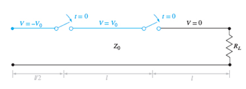
Figure 10.39 See Problem 10.43.
In Figure 10.39, RL = Z0 and Rg = Z0 /3. The switch is closed at t = 0. Determine and plot as functions of time (a) the voltage across RL; (b) the voltage across Rg; (c) the current through the battery.
Expert Solution & Answer
Want to see the full answer?
Check out a sample textbook solution
Students have asked these similar questions
Obtain an expression for the power dissipated in the 10 Ω resistor of Fig. 10,49. assuming no transients present.
Which row represent the most stable system and why? nyquist and root locus plot attached.
A transmitter supplied by 100W power is used with an antenna having a gain of 5dBi. *Calculate the EIRP in dBm*Calculate the power density (µW/m^2) at distance of 10km.
Chapter 10 Solutions
Engineering Electromagnetics
Ch. 10 - The parameters of a certain transmission line...Ch. 10 - A sinusoidal wave on a transmission line is...Ch. 10 - Prob. 10.3PCh. 10 - A sinusoidal voltage V0, frequency , and phase...Ch. 10 - Two voltage waves of equal amplitude V0 and radian...Ch. 10 - A 50 load is attached to a 50-m section of the...Ch. 10 - Prob. 10.7PCh. 10 - An absolute measure of power is the dBm scale, in...Ch. 10 - A 100-m transmission line is used to propagate a...Ch. 10 - Two lossless transmission lines having different...
Ch. 10 - Two voltage waves of equal amplitude V0, which...Ch. 10 - In a circuit in which a sinusoidal voltage source...Ch. 10 - The skin effect mechanism in transmission lines is...Ch. 10 - A lossless transmission line having characteristic...Ch. 10 - Figure 10.29 See Problem 10.15. For the...Ch. 10 - A 100 lossless transmission line is connected to a...Ch. 10 - Determine the average power absorbed by each...Ch. 10 - The line shown in Figure 10.31 is lossless. Find s...Ch. 10 - A lossless transmission line is 50 cm in length...Ch. 10 - (a) Determine s on the transmission line of Figure...Ch. 10 - Prob. 10.21PCh. 10 - Prob. 10.22PCh. 10 - The normalized load on a lossless transmission...Ch. 10 - Prob. 10.24PCh. 10 - Prob. 10.25PCh. 10 - A 75 lossless line is of length 1.2 . It is...Ch. 10 - Prob. 10.27PCh. 10 - The wavelength on a certain lossless line is 10...Ch. 10 - Prob. 10.29PCh. 10 - A two-wire line constructed of lossless wire of...Ch. 10 - In order to compare the relative sharpness of the...Ch. 10 - In Figure 10.17, let ZL=250 and Z0=50. Find the...Ch. 10 - In Figure 10.17, let ZL=100+j150 and Z0=100. Find...Ch. 10 - The lossless line shown in Figure 10.35 is...Ch. 10 - Prob. 10.35PCh. 10 - The two-wire lines shown in Figure 10.36 are all...Ch. 10 - Prob. 10.37PCh. 10 - Repeat Problem 10.37, with, Z0=50 and RL=Rg=25....Ch. 10 - In the transmission line of Figure 10.20, Z0=50,...Ch. 10 - In the charged line of Figure 10.25, the...Ch. 10 - In the transmission line of Figure 10.37, the...Ch. 10 - Figure 10.38 See Problem 10.42. A simple frozen...Ch. 10 - Figure 10.39 See Problem 10.43. In Figure 10.39,...
Knowledge Booster


Learn more about
Need a deep-dive on the concept behind this application? Look no further. Learn more about this topic, electrical-engineering and related others by exploring similar questions and additional content below.Similar questions
- A point source q1= 20nC is located at S(1,4 ), determine some points near S ,where the magnitude of electric field E is equal to 30V/marrow_forwardUsing Northon's Theorem, solve for Vo if R = 1, Vs = 2, and Is = 1.arrow_forward1. Discuss in detail the construction of a Directional Coupler. 2. Discuss in detail whether the incident energy can be sampled or not with pick up probe at port ‘4’.arrow_forward
- Given that D = 10sinϴar + 2 cosϴaϴ .Evaluate both sides of the divergence theorem for the volume enclosed by the shell r = 2.arrow_forwardGiven that D= (10r3/4 ) ar (c/m2) in cylindrical coordinates, evaluate both sides of the divergence theorem for the volume enclosed by r = 1m, r =2m and Ƶ= 0 and Ƶ= 10arrow_forwardAn optical fiber link with a distance of 30km long has a loss of 0.3dB/km. a) Calculate the minimum optical power level that must be launched into the fiber to maintain an optical power level of 3.0W at the receiving end.b) Estimate the required input power if the fiber has a loss of 0.6dB/km.c) Differentiate, with the aid of diagrams, the types of these dispersions and its effect on the transmission distance. (i) Modal Dispersion(ii) Chromatic Dispersion(iii) Polarization Mode Dispersionarrow_forward
- Show thatarrow_forwardSolve the problem. PROVIDE THE GIVEN, REQUIRED, EQUATION, SOLUTION, AND FINAL ANSWER WAO’s frequency is 85.2 MHz. What does this mean, and what period does this correspond to?arrow_forwardA 132kV line with 1.956 cm diameter polished conductors is built so that corona takes place if the line voltage exceeds 75kV per phase. If the value of potential gradient at which ionization occurs cab be taken as 32kV (Max) per cm and air density factor 0.91. Distance between conductors is 1.21 meters. The corona loss isarrow_forward
- Use the free space model to compute the free space path loss for a 900 MHz signal over a distance of 200 meters. Express your answer in dB. state the answer in the correct units and show all your computations to receive creditarrow_forward5/The Voltage Regulation of a Transmission Line (in the simulator) depends on which parameter/s? A. Both the Transmission Line Resistance and Inductance B. The Transmission Line Shunt Capacitance only C. The Transmission Line Inductance only D. The Transmission Line Resistance onlyarrow_forwardThe effective span of an antenna is 2.147 m2 at an operating frequency of 100MHz. The antenna has no conduction or dielectric loss. The input impedance of the antenna is 75Ω and it is connected to a 50Ω transmission line. Find the directionality of the antenna system. (The term "system" here refers to the effects of binding to the transmission line.) It will be assumed that there is no polarization loss.arrow_forward
arrow_back_ios
SEE MORE QUESTIONS
arrow_forward_ios
Recommended textbooks for you
 Introductory Circuit Analysis (13th Edition)Electrical EngineeringISBN:9780133923605Author:Robert L. BoylestadPublisher:PEARSON
 Delmar's Standard Textbook Of ElectricityElectrical EngineeringISBN:9781337900348Author:Stephen L. HermanPublisher:Cengage Learning
 Programmable Logic ControllersElectrical EngineeringISBN:9780073373843Author:Frank D. PetruzellaPublisher:McGraw-Hill Education
 Fundamentals of Electric CircuitsElectrical EngineeringISBN:9780078028229Author:Charles K Alexander, Matthew SadikuPublisher:McGraw-Hill Education
 Electric Circuits. (11th Edition)Electrical EngineeringISBN:9780134746968Author:James W. Nilsson, Susan RiedelPublisher:PEARSON
 Engineering ElectromagneticsElectrical EngineeringISBN:9780078028151Author:Hayt, William H. (william Hart), Jr, BUCK, John A.Publisher:Mcgraw-hill Education,
Introductory Circuit Analysis (13th Edition)
Electrical Engineering
ISBN:9780133923605
Author:Robert L. Boylestad
Publisher:PEARSON
Delmar's Standard Textbook Of Electricity
Electrical Engineering
ISBN:9781337900348
Author:Stephen L. Herman
Publisher:Cengage Learning
Programmable Logic Controllers
Electrical Engineering
ISBN:9780073373843
Author:Frank D. Petruzella
Publisher:McGraw-Hill Education
Fundamentals of Electric Circuits
Electrical Engineering
ISBN:9780078028229
Author:Charles K Alexander, Matthew Sadiku
Publisher:McGraw-Hill Education
Electric Circuits. (11th Edition)
Electrical Engineering
ISBN:9780134746968
Author:James W. Nilsson, Susan Riedel
Publisher:PEARSON
Engineering Electromagnetics
Electrical Engineering
ISBN:9780078028151
Author:Hayt, William H. (william Hart), Jr, BUCK, John A.
Publisher:Mcgraw-hill Education,
How does an Antenna work? | ICT #4; Author: Lesics;https://www.youtube.com/watch?v=ZaXm6wau-jc;License: Standard Youtube License