
Concept explainers
(a)
The value of resistor R .
(a)
Answer to Problem 10.65P
Explanation of Solution
Given:
Calculation:
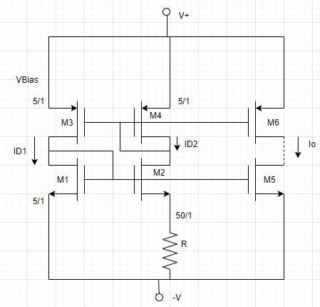
The given circuit is,

According to the statement
Also,
Now calculate R ,
Substitute the given values,
Conclusion:
(b)
The biased voltage difference (
(b)
Answer to Problem 10.65P
Explanation of Solution
Given:
Calculation:
The given circuit is,

According to the circuit,
Now the drain current expression is,
From equation (2),
Now the drain current expression is,
Now from equation (1),
Conclusion:
(c)
The ratio
(c)
Answer to Problem 10.65P
Explanation of Solution
Given:
Calculation:
The given circuit is,
According to the circuit,
Now the drain current expression is,
From equation (2),
Now the drain current expression is,
The expression for current
On substituting the given values,
The expression for current
On substituting the given values,
Conclusion:
Want to see more full solutions like this?
Chapter 10 Solutions
Microelectronics: Circuit Analysis and Design


- kindly explain this part ,, how sinc100t is represemted in frequency domainarrow_forwardA superheterodyne receiver is to tune the range 88.1MHz to 107.1MHz. The RF circuit inductance is 1μH. Low-side injection is used.a. Calculate the minimum capacitance of the variable capacitor in the RF circuitb. Calculate the RF circuit capacitance tuning ratio c. If the receiver has a single converter stage and IF of 800kHz, calculate the capacitance tuning ratio of the local oscillator d. If the maximum capacitance of the variable capacitor of the local oscillator is 0.2pF, calculate the minimum capacitance e. If the receiver has a single converter stage and IF of 800kHz, calculate the image frequency of 103.7MHzf. Calculate the IFRR (in dB) of (e) if Q of the preselector is 50 g. To increase the IFRR of (e) to 40dB, double conversion is used. What must be the frequency of the 1st IF?arrow_forwardThe quality factor for the TE101 mode in a hollow rectangular resonator is given as; What should be the size of the resonator so that the quality factor of a hollow cubic resonator made of a conductor with a skin thickness of 0.50 nm is 25,000?arrow_forward
- An ac supply of 230V is applied to a HWR through a turn’s ratio of 10:1. Assume Rf=10Ω, RL=100Ω. Find the γ, η, TUF, PF, PIV?arrow_forwardElectronic Since k = 0.35x10^3, VGSQ = 6.2 V, VGS(Th) = 2.4 V, RF = 100 MΩ, RG = 10 MΩ, RD = 7.6 kΩ, RS = 2.2 kΩ and RL = 21 kΩ in the circuit in the figure, the output voltage In which option is the amplitude value (Vout) given correctly? NOTE-1: E-MOSFET output impedance is rd = 70 kΩ and should be taken into account in calculations. NOTE-2: Capacitors are of negligible size at mid-band frequency. NOTE-3: It is within the 5 kHz mid-band frequency.arrow_forwardWith reference to the network shown in Fig. 10.19, find the inputimpedance Zin that would be measured between terminals: (a) a and g;(b) b and g; (c) a and b.arrow_forward
- Determine the Norton equivalent of the circuit in Fig. 10.30 as seen fromterminals a‑b. Use the equivalent to find Io ?arrow_forwardDetermine its sensitivity value, then if S changes from 100 to 120 what is the percentage effect to the entire system's performancearrow_forwardProblem 1 The transistor parameters for the given circuit are β = 100, VBE (on) = 0.7 V, and VA = ∞. Determine the midband gain AvM, corner frequencies fL and fH, and bandwidth BW of the given amplifier. Problem 2 Determine the corner frequencies and limiting horizontal asymptotes of a commonemitter amplifier with an emitter bypass capacitor. For the given circuit, RE = 4 kΩ, RC = 2 kΩ, RS = 0.5 kΩ, CE = 1 μF, V + = 5 V, and V − = −5 V. The transistor parameters are: β = 100, VBE(on) = 0.7 V, and ro = ∞.arrow_forward
- ı just need the fınal answer Since Vcc = 20 V, RS = 3 kΩ, RB = 380 kΩ, RC = 1.2 kΩ, RE = 2.2 kΩ, RL = 911 Ω and β = 90 in the circuit in the figure, find the value of the output voltage (Vo). NOTE-1: It is within the 1 kHz mid-band frequency and the capacitors are negligible at this frequency. NOTE-2: The output impedance (r0) of the transistor will be neglected. a. 64,14 mV b. 83,88 mV c. 93,75 mV d. 74,01 mV e. 103,62 mV f. 24,67 mV g. 34,54 mV h. 49,34 mVarrow_forwardi) A communication system employs a continuous source. The channel noise is white and Gaussian. The bandwidth of the source output is 10 MHz and signal to noise power ratio at the receiver is 100. (a) Determine the channel capacity. (b) If the signal to noise ratio drops to 10, how much bandwidth is needed to achieve the same channel capacity as in (a). (c) If the bandwidth is decreased to 1 MHz, what S/N ratio is required to maintain the same channel capacity as in (a).arrow_forwardFor the circuit shown, let VCC = 3.3 V, RE = 500 Ω, RC = 4 kΩ, R1 = 85 kΩ, R2 = 35 kΩ, and β = 150. Using approximation, determine the Q-point parameters: IBQ, ICQ, and VCEQ. Indicate the exact numerical values, following the given unit.arrow_forward
 Introductory Circuit Analysis (13th Edition)Electrical EngineeringISBN:9780133923605Author:Robert L. BoylestadPublisher:PEARSON
 Delmar's Standard Textbook Of ElectricityElectrical EngineeringISBN:9781337900348Author:Stephen L. HermanPublisher:Cengage Learning
 Programmable Logic ControllersElectrical EngineeringISBN:9780073373843Author:Frank D. PetruzellaPublisher:McGraw-Hill Education
 Fundamentals of Electric CircuitsElectrical EngineeringISBN:9780078028229Author:Charles K Alexander, Matthew SadikuPublisher:McGraw-Hill Education
 Electric Circuits. (11th Edition)Electrical EngineeringISBN:9780134746968Author:James W. Nilsson, Susan RiedelPublisher:PEARSON
 Engineering ElectromagneticsElectrical EngineeringISBN:9780078028151Author:Hayt, William H. (william Hart), Jr, BUCK, John A.Publisher:Mcgraw-hill Education,