
Fundamentals of Geotechnical Engineering (MindTap Course List)
5th Edition
ISBN: 9781305635180
Author: Braja M. Das, Nagaratnam Sivakugan
Publisher: Cengage Learning
expand_more
expand_more
format_list_bulleted
Concept explainers
Videos
Textbook Question
Chapter 12, Problem 12.7P
The table gives the standard penetration numbers determined from a sandy soil deposit in the field:
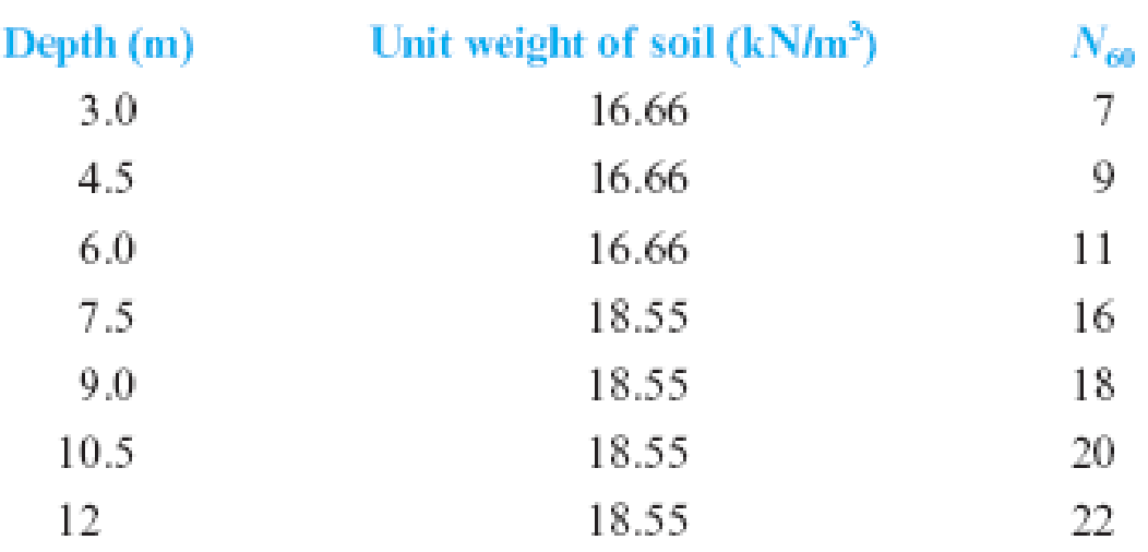
Using Eq. (12.19), determine the variation of the peak soil friction angle,
Expert Solution & Answer

Trending nowThis is a popular solution!

Students have asked these similar questions
A cut slope of h= 7m was excavated in a saturated clay with a slope of angle beta = 45 degrees with the horizontal.
The Previous explorations showed that a rock layer was located at a depth of 14 m.
Given that,
c = 60 kN/m² and unit weight = 17 kN / (m ^ 3) . Determine the factor of safety.
Following are the standard penetration numbers determined from a sandy soil in the field: Using Eq. (3.30), determine the variation of the peak soil friction angle, Φ'. Estimate an average value of Φ' for the design of a shallow foundation. (Note: For depth greater than 20 ft, the unit weight of soil is 118 lb/ft3.)
Determine the relative density at each depth using attached equation. Assume moderately compressible sand and hence Qc = 1.
Chapter 12 Solutions
Fundamentals of Geotechnical Engineering (MindTap Course List)
Knowledge Booster


Learn more about
Need a deep-dive on the concept behind this application? Look no further. Learn more about this topic, civil-engineering and related others by exploring similar questions and additional content below.Similar questions
- A shallow square foundation for a column is to be constructed. It must carry a net vertical load of 1000 kN. The soil supporting the foundation is sand. The standard penetration numbers (N60) obtained from field exploration are as follows: FIG. 17.15 The groundwater table is located at a depth of 12 m. The unit weight of soil above the water table is 15.7 kN/m3, and the saturated unit weight of soil below the water table is 18.8 kN/m3. Assume that the depth of the foundation will be 1.5 m and the tolerable settlement is 25 mm. Determine the size of the foundation.arrow_forwardRefer to Problem 17.7 and Figure 17.16. Suppose a footing (1.5 m 1.5 m) is constructed at a depth of 1 m. a. Estimate the design values for N60 and . b. What is the net allowable load that the footing can carry? The maximum allowable 17.7 settlement is 25 mm. Use Eqs. (16.56) and (16.61). Refer to the boring log shown in Figure 17.16. Estimate the average drained friction angle, , using the Kulhawy and Mayne correlation [Eq. (17.24)]. Assume pa 100 kN/m2. Figure 17.16arrow_forward44.) A 5 m-thick clay (Gs = 2.65, water content = 0.28) is overlain by a 4.50m-thick layer of sand (Gs = 2.60, e = 0.70, S = 0.85). The ground water table is located 4.50 m from the ground surface. Compute for the following: 1. At what depth would the vertical effective stress be equal to 120 kPa? 2. What is the vertical effective stress at a depth 9 m below the ground surface? 3. The depth of excavation required to reduce the effective stress at the bottom of the clay layer by 100 kPa. Question 1: A. 1.94 Question 1: B. 3.99 Question 1: C. 6.44 Question 1: D. 8.49 Question 2: A. 168.9 Question 2: B. 44.1 Question 2: C. 120.1 Question 2: D. 124.8 Question 3: A. 1.83 Question 3: B. 7.67 Question 3: C. 3.17 Question 3: D. 6.33arrow_forward
- 2. How to evaluate the rock properties according to the distribution curves and give at least two coefficients of that.arrow_forwardAn embankment consists of clay fill for which c=25 kPa and angle of internal friction is 260 (from consolidated undrained test with pore pressure measurement) The weight of fill per unit volume is 18.64 kN/m3. Compute the effective stress in kPa at a depth of 20 m. If the pore pressure at this point is shown by a piezometer to be 180 kPa. a. 62.5 b. 372.8 c. 192.8 d. 21.6arrow_forward9.1 Through 9.3 A soil profile consisting of three layers is shown in Figure 9.25.Calculate the values of σ, u, and σ′ at points A, B, C, and D for the following cases. Ineach case, plot the variations of σ, u, and σ′ with depth. Characteristics of layers 1, 2,and 3 for each case are given below:arrow_forward
arrow_back_ios
arrow_forward_ios
Recommended textbooks for you
 Fundamentals of Geotechnical Engineering (MindTap...Civil EngineeringISBN:9781305635180Author:Braja M. Das, Nagaratnam SivakuganPublisher:Cengage Learning
 Principles of Foundation Engineering (MindTap Cou...Civil EngineeringISBN:9781337705028Author:Braja M. Das, Nagaratnam SivakuganPublisher:Cengage Learning
 Principles of Geotechnical Engineering (MindTap C...Civil EngineeringISBN:9781305970939Author:Braja M. Das, Khaled SobhanPublisher:Cengage Learning
 Principles of Foundation Engineering (MindTap Cou...Civil EngineeringISBN:9781305081550Author:Braja M. DasPublisher:Cengage Learning
Fundamentals of Geotechnical Engineering (MindTap...
Civil Engineering
ISBN:9781305635180
Author:Braja M. Das, Nagaratnam Sivakugan
Publisher:Cengage Learning
Principles of Foundation Engineering (MindTap Cou...
Civil Engineering
ISBN:9781337705028
Author:Braja M. Das, Nagaratnam Sivakugan
Publisher:Cengage Learning
Principles of Geotechnical Engineering (MindTap C...
Civil Engineering
ISBN:9781305970939
Author:Braja M. Das, Khaled Sobhan
Publisher:Cengage Learning
Principles of Foundation Engineering (MindTap Cou...
Civil Engineering
ISBN:9781305081550
Author:Braja M. Das
Publisher:Cengage Learning
Types of Foundation in building construction in detail - Civil Engineering Videos; Author: Civil Engineers;https://www.youtube.com/watch?v=7sl4KuM4UIE;License: Standard YouTube License, CC-BY
Types of Foundation || Foundation Engineering; Author: Civil Engineering;https://www.youtube.com/watch?v=AFLuAKGhanw;License: Standard Youtube License