
Loose Leaf for Fundamentals of Electric Circuits Format: LooseLeaf
6th Edition
ISBN: 9781259657054
Author: Alexander
Publisher: Mcgraw Hill Publishers
expand_more
expand_more
format_list_bulleted
Concept explainers
Videos
Textbook Question
Chapter 12, Problem 84CP
Figure 12.76 displays a three-phase delta-connected motor load which is connected to a line voltage of 440 V and draws 4 kVA at a power factor of 72 percent lagging. In addition, a single 1.8 kVAR capacitor is connected between lines a and b, while a 800-W lighting load is connected between line c and neutral. Assuming the abc sequence and taking Van = Vp
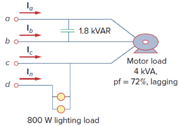
Figure 12.76
Expert Solution & Answer
Want to see the full answer?
Check out a sample textbook solution
Students have asked these similar questions
The length of a three-phase power transmission line with a nominal operating voltage of 69 kV is 16km. The impedance of the transmission line per unit length is 0.125 + j0.4375 ohm/ km. At the end of the line, a 70 MVA star connected load with a power factor of 0.8 back under 69 kV interphase voltage is fed. Capacitive circuit element with a capacitance of 19.14 mikro F / phase is placed as shunt at the end of the transmission line. According to these given;
a) Line head voltage and current,
b) Calculate the active and reactive power per line.
S.4) the length of a three-phase power transmission line with a Nominal operating voltage of 69 kV is 16km. The impedance of the transmission line per unit length is 0.125 + j0.4375 ohm/km. From the end of the line, a 56 MW star connected load is fed with a power coefficient of 0.8 back under a 64 kV interphase voltage. If the line head voltage of the transmission line is 69 kV, calculate the capacity and power of the star-connected capacitor to be shunted into the load connected to the end of the line.
A 69 – kV, 3 – phase short transmission line is 16 km long. The line has a per phase series impedance of 1.125 + j0.4375 ohm per km. Shunt capacitors are installed at the receiving end to improve the line performance. The line delivers 70 MVA, 0.80 lagging power factor at 64 kV. Determine the receiving end line real power when the sending end voltage is 69 kV.
Chapter 12 Solutions
Loose Leaf for Fundamentals of Electric Circuits Format: LooseLeaf
Ch. 12.2 - Given that Vbn=22030V, find Van and Vcn, assuming...Ch. 12.3 - A Y-connected balanced three-phase generator with...Ch. 12.4 - One line voltage of a balanced Y-connected source...Ch. 12.5 - A positive-sequence, balanced -connected source...Ch. 12.6 - In a balanced -Y circuit, Vab=44015 and ZY = (12 +...Ch. 12.7 - For the Y-Y circuit in Practice Prob. 12.2,...Ch. 12.7 - Calculate the line current required for a 30-kW...Ch. 12.7 - Assume that the two balanced loads in Fig....Ch. 12.8 - The unbalanced -load of Fig. 12.24 is supplied by...Ch. 12.8 - Find the line currents in the unbalanced...
Ch. 12.9 - Prob. 11PPCh. 12.9 - For the unbalanced circuit in Fig. 12.32, use...Ch. 12.10 - Repeat Example 12.13 for the network in Fig. 12.24...Ch. 12.10 - Let the line voltage VL = 208 V and the wattmeter...Ch. 12.10 - If the load in Fig. 12.35 is delta-connected with...Ch. 12 - What is the phase sequence of a three-phase motor...Ch. 12 - If in an acb phase sequence, , then Vcn is:Ch. 12 - Which of these is not a required condition for a...Ch. 12 - Prob. 4RQCh. 12 - Prob. 5RQCh. 12 - In a Y-Y system, a line voltage of 220 V produces...Ch. 12 - In a - system, a phase voltage of 100 V produces a...Ch. 12 - When a Y-connected load is supplied by voltages in...Ch. 12 - Prob. 9RQCh. 12 - Prob. 10RQCh. 12 - If Vab = 400 V in a balanced Y-connected...Ch. 12 - What is the phase sequence of a balanced...Ch. 12 - Given a balanced Y-connected three-phase generator...Ch. 12 - A three-phase system with abc sequence and VL =...Ch. 12 - For a Y-connected load, the time-domain...Ch. 12 - Using Fig. 12.41, design a problem to help other...Ch. 12 - Obtain the line currents in the three-phase...Ch. 12 - In a balanced three-phase Y-Y system, the source...Ch. 12 - A balanced Y-Y four-wire system has phase voltages...Ch. 12 - For the circuit in Fig. 12.43, determine the...Ch. 12 - In the Y- system shown in Fig. 12.44, the source...Ch. 12 - Using Fig. 12.45, design a problem to help other...Ch. 12 - In the balanced three-phase Y- system in Fig....Ch. 12 - Obtain the line currents in the three-phase...Ch. 12 - The circuit in Fig. 12.48 is excited by a balanced...Ch. 12 - A balanced delta-connected load has a phase...Ch. 12 - A positive sequence wye-connected source where ,...Ch. 12 - If Van = 22060 V in the network of Fig. 12.49,...Ch. 12 - For the - circuit of Fig. 12.50, calculate the...Ch. 12 - Prob. 20PCh. 12 - Three 440-V generators form a delta-connected...Ch. 12 - Find the line currents IaA, IbB, and IcC in the...Ch. 12 - A balanced delta connected source is connected to...Ch. 12 - A balanced delta-connected source has phase...Ch. 12 - In the circuit of Fig. 12.54, if , , , find the...Ch. 12 - Using Fig. 12.55, design a problem to help other...Ch. 12 - A -connected source supplies power to a...Ch. 12 - The line-to-line voltages in a Y-load have a...Ch. 12 - A balanced three-phase Y- system has V rms and Z =...Ch. 12 - In Fig. 12.56, the rms value of the line voltage...Ch. 12 - A balanced delta-connected load is supplied by a...Ch. 12 - Design a problem to help other students better...Ch. 12 - A three-phase source delivers 4.8 kVA to a...Ch. 12 - A balanced wye-connected load with a phase...Ch. 12 - Three equal impedances, 60 + j30 each, are...Ch. 12 - A 4200-V, three-phase transmission line has an...Ch. 12 - The total power measured in a three-phase system...Ch. 12 - Given the circuit in Fig. 12.57 below, find the...Ch. 12 - Find the real power absorbed by the load in Fig....Ch. 12 - For the three-phase circuit in Fig. 12.59, find...Ch. 12 - A balanced delta-connected load draws 5 kW at a...Ch. 12 - A balanced three-phase generator delivers 7.2 kW...Ch. 12 - Refer to Fig. 12.48. Obtain the complex power...Ch. 12 - A three-phase line has an impedance of 1 + j3 per...Ch. 12 - A balanced wye-connected load is connected to the...Ch. 12 - A three-phase load consists of three 100-...Ch. 12 - The following three parallel-connected three-phase...Ch. 12 - A balanced, positive-sequence wye-connected source...Ch. 12 - Each phase load consists of a 20- resistor and a...Ch. 12 - A balanced three-phase source with VL = 240 V rms...Ch. 12 - Consider the wye-delta system shown in Fig. 12.60....Ch. 12 - A four-wire wye-wye circuit has...Ch. 12 - Using Fig. 12.61, design a problem that will help...Ch. 12 - A balanced three-phase Y-source with VP = 880 V...Ch. 12 - A three-phase supply, with the line-to-line...Ch. 12 - Using Fig. 12.63, design a problem to help other...Ch. 12 - Determine the line currents for the three-phase...Ch. 12 - Solve Prob. 12.10 using PSpice or MultiSim. For...Ch. 12 - The source in Fig. 12.65 is balanced and exhibits...Ch. 12 - Use PSpice or MultiSim to determine Io in the...Ch. 12 - Given the circuit in Fig. 12.67, use PSpice or...Ch. 12 - Using Fig. 12.68, design a problem to help other...Ch. 12 - Use PSpice or MultiSim to find currents IaA and...Ch. 12 - For the circuit in Fig. 12.58, use PSpice or...Ch. 12 - A balanced three-phase circuit is shown in Fig....Ch. 12 - A three-phase, four-wire system operating with a...Ch. 12 - As shown in Fig. 12.72, a three-phase four-wire...Ch. 12 - Meter readings for a three-phase wye-connected...Ch. 12 - A certain store contains three balanced...Ch. 12 - The two-wattmeter method gives P1=1200W and...Ch. 12 - In Fig. 12.73, two wattmeters are properly...Ch. 12 - If wattmeters W1 and W2 are properly connected...Ch. 12 - For the circuit displayed in Fig. 12.74, find the...Ch. 12 - Predict the wattmeter readings for the circuit in...Ch. 12 - Prob. 75PCh. 12 - Show that the I2R losses will be higher for a...Ch. 12 - A three-phase generator supplied 10 kVA at a power...Ch. 12 - Prob. 78CPCh. 12 - A balanced three-phase generator has an abc phase...Ch. 12 - A balanced three-phase source furnishes power to...Ch. 12 - A professional center is supplied by a balanced...Ch. 12 - A balanced three-phase system has a distribution...Ch. 12 - A commercially available three-phase inductive...Ch. 12 - Figure 12.76 displays a three-phase...Ch. 12 - Design a three-phase heater with suitable...Ch. 12 - For the single-phase three-wire system in Fig....Ch. 12 - Consider the single-phase three-wire system shown...
Knowledge Booster


Learn more about
Need a deep-dive on the concept behind this application? Look no further. Learn more about this topic, electrical-engineering and related others by exploring similar questions and additional content below.Similar questions
- 2. A 12500 kVA load is supplied at a power factor of 0·8 lagging by a 3-phase transmission line whosevoltage is to be maintained at 33 kV at both ends. Determine the capacity of the synchronous condenserto be installed at the receiving end. The impedance of the line is (4 + j 12) ohms per phase. solution is [11490 kVAR]arrow_forwardA 3-phase, 60 Hz, 55 km long overhead line supplies 575 kW at 11 kV, 0.9 p.f. lagging. The line resistance is 3.5 Ω per phase and line inductance is 10 mH per phase. Calculate the Reactance of the Line, Current flowing through the transmission line, Sending end voltage, Voltage regulation and Efficiency of transmission. Inductive Reactance= Current flowing through the transmission line= Sending end Voltage=arrow_forwardhallo A 69-kV, three-phase short transmission line is 16 km long. The line has a per phase series impedance of 0.125 + j0.4375 ohm per km. Determine the sending end voltage, voltage regulation, the sending end power, and the transmission efficiency when the line delivers 70 MVA, 0.8 lagging power factor at 64 kV. 120 MW, unity power factor at 64 kV. Use lineperf program to verify your results.arrow_forward
- A 3-phase transmission line delivers 4500 KVA at a p.f. 0.8 lagging to a load. If the sending end voltage is 33 kV, determine (a) the receiving end voltage (b) line current (c) transmission efficiencv. The resistance and reactance of each conductor are 5.31 ohms and 5.54 ohms respectively.arrow_forwarda) A balanced three-phase delta-connected overhead line has constants A = 0.9/10°, B = 50/64° Ω . The receiving end line voltage is held at 330kV. The line is to transmit 1000MWat a power factor of 0.9 lagging at the receiving end. Determine the following: i) Receiving end current ii) Sending end voltage b) If the line is now to transmit 900 MW at a leading power factor of 0.8 at the receiving end determine the following: i) Receiving end current ii) Sending end current PLEASE Comment on your answers to a) and b) PLEASE I NEED CORRECT SOLUTION. THANK YOU.arrow_forwardA 3-phase, 50 Hz, overhead transmission line delivers 10 MW at 0·8 p.f. lagging and at 66 The resistance and inductive reactance of the line per phase are 10 W and 20 W respectively while capacitance admittance is 4 × 10- 4 siemen. Calculate : (i)the sending end current (ii) sending end voltage (line-to-line) (iii) sending end power factor (iv) transmission efficiency Use nominal T method.arrow_forward
- A single phase, 50 Hz, overhead transmission line supplies 1500 kW at 31 kV, 0.8 p.f. lagging. The total resistance and line inductive reactance of the line are 3.75 Ω and 7.5 Ω respectively. Calculate the sending end voltage, voltage regulation, sending end power factor and efficiency of transmission.arrow_forwardThe following three-phase loads are connected to a short transmission line with impedance per wire of 4 + j7 ohms: Load 1: Resistive load drawing 80 A, Load 2: Capacitor drawing 60 A, Load 3: Inductive load drawing 50 A at 80 % power factor. What is the sending end power factor for a receiving end voltage of 34.5 kV? a. 96 % b. 97 % c. 98 % d. 99 %arrow_forwardA single phase transmission line is delivering 470 kVA load at 14 kV. Its resistance is 4 Ω and inductive reactance is 8 Ω. If the load power factor is 0.9 lagging. Determine the 1Current through the line: 2Sending end voltage: 3Sending end power factor: 4Regulation of transmission line: 5Efficiency of transmission line:arrow_forward
- A three-phase transmission line has resistance and inductive reactance of 25V and 90V, respectively. With no load at the receiving end, a synchronous compensator there takes a current lagging by 90; the voltage is 145 kV at the sending end and 132 kV at the receiving end. Calculate the value of the current taken by the compensator. When the load at the receiving end is 50MW, it is found that the line can operate with unchanged voltages at the sending and receiving ends, provided that the compensator takes the same current as before, but now leading by 90. Calculate the reactive power of the loadarrow_forwardA three-phase, four wire, ABC system with a line voltage of 380 Volt, has three impedances of Z =10 /45ᴼ in aWye connection, assumed that VAB is the reference vector. Determine the line current and draw thevoltage-current phasor diagram.arrow_forwardA three-phase line with an impedance of (0.2+j1.0)/ phase feeds three balanced three-phase loads connected in parallel. Load 1: Absorbs a total of 150 kW and 120 kvar. Load 2: Delta connected with an impedance of (150j48)/phase. Load 3: 120 kVA at 0.6 PF leading. If the line-to-neutral voltage at the load end of the line is 2000 v (rms), determine the magnitude of the line-to-line voltage at the source end of the line.arrow_forward
arrow_back_ios
SEE MORE QUESTIONS
arrow_forward_ios
Recommended textbooks for you
 Power System Analysis and Design (MindTap Course ...Electrical EngineeringISBN:9781305632134Author:J. Duncan Glover, Thomas Overbye, Mulukutla S. SarmaPublisher:Cengage Learning
Power System Analysis and Design (MindTap Course ...
Electrical Engineering
ISBN:9781305632134
Author:J. Duncan Glover, Thomas Overbye, Mulukutla S. Sarma
Publisher:Cengage Learning
How do Electric Transmission Lines Work?; Author: Practical Engineering;https://www.youtube.com/watch?v=qjY31x0m3d8;License: Standard Youtube License