
Concept explainers
Videos
The maximum and minimum output voltage in the MC14573 circuit such that op-amp remains biased in its linear region.
Answer to Problem 13.10TYU
The input common mode voltage range for the MC14573 op-amp is
Explanation of Solution
Given:
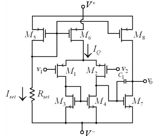
Following is given circuit of the MC14573 op-amp equivalent circuit
Given data,
The transistor parameters are
And the circuit parameters are
The given width to length ratio of
Calculation:
For transistors
Hence,
Now assuming the transistor
currents are given as
We know that the reference current and source to gate voltage is also related by
Now combining equation (1) and (2) yields the source to gate voltage of
Using quadratic equation,
Hence,
Now from equation (1) we have
The reference current is
Similarly, the source to gate voltage of
We know that
Therefore, the source-to-drain saturation voltage is
Now the maximum input voltage is given as
Therefore, the maximum input voltage is
Now for transistor
Therefore,
Now
Where
Now
Therefore, the source-to-gate voltage of
We know that
Therefore, the source-to-drain saturation voltage is
Now the minimum input voltage is given as
Therefore, the minimum input voltage is
The input common mode voltage range for the MC14573 op-amp is
Want to see more full solutions like this?
Chapter 13 Solutions
Microelectronics: Circuit Analysis and Design


- Determine the ICQ and VCEQ of the circuit. Assume ßDC = 85. Then plot the DCLL and Q-point of the circuitarrow_forwardDetermine the closed-loop voltage gain of the circuit shown in FigureP13.10 , assuming an ideal op amp.arrow_forward1. Describe the high frequency response and phase shift for BJT and FET transistors using MillersTheorem ata) Input RC circuitb) Output RC circuit The subject : Analogue Electronics IIarrow_forward
- The transistor parameters for the circuit shown are VTN = 0.4 V, Kn=0.5mA/V2, and λ = 0.(a) Find (i) the quiescent drain current IDQ and (ii) Draw the small-signal equivalentcircuit and find the small signal transistor parameters.(b) Determine the transfer function.(c) Find the output resistance Rof.arrow_forward2: Determine the value of small-signal parameter rπ of Q1 for the circuit shown below.arrow_forwardDescription and discussion of Discussed active band pass filter in the circuit belowarrow_forward
- calculate the loop gain voltage for the circuit shown in this image given that the unity gain frequency of the LF157A is 20MHZ and output for 1kHz and 10 MHz.arrow_forward(a) Assume M1 and M2 are identical MOSFETs operating in the triode (linear) region of operation. What is the value of the output voltage vOUT when vIN> VT (the threshold voltage for the MOSFETs) assuming RON = 0 Ω where RON is the on-resistance of the MOSFETS.arrow_forwardDraw a pnp version of the differential amplifier as shown.arrow_forward
- The transistor parameters for the differential amplifier shown in Figure P11.32 are VT N = 0.5 V, k n = 80 µA/V2, W/L = 4, and λ = 0. (a) Find RD and IQ such that ID1 = ID2 = 80 µA and vO2 = 2 V when v1 = v2 = 0. (b) Draw the dc load line, and plot the Q-point for M2. (c) What is the maximum common-mode input voltage? Figure p11.32arrow_forwardUsing 741 op amp, design a suitable circuit to generate Binary Phase Shift Keyiing(BFSK) modulator. Design should perform in such a way that the BFSK output should contain a frequency of f1=2kHz when message signal is low and f2 =4kHz when the message signal is high. Take the frequency of message signal as 200Hz. Draw the clear circuit diagram and calculate the values of resistors and capacitors used.arrow_forwardGiven the differential amplifier circuit below. Determine the following: emitter current, differential mode voltage gain, common mode voltage gain and CMRR.arrow_forward
 Introductory Circuit Analysis (13th Edition)Electrical EngineeringISBN:9780133923605Author:Robert L. BoylestadPublisher:PEARSON
 Delmar's Standard Textbook Of ElectricityElectrical EngineeringISBN:9781337900348Author:Stephen L. HermanPublisher:Cengage Learning
 Programmable Logic ControllersElectrical EngineeringISBN:9780073373843Author:Frank D. PetruzellaPublisher:McGraw-Hill Education
 Fundamentals of Electric CircuitsElectrical EngineeringISBN:9780078028229Author:Charles K Alexander, Matthew SadikuPublisher:McGraw-Hill Education
 Electric Circuits. (11th Edition)Electrical EngineeringISBN:9780134746968Author:James W. Nilsson, Susan RiedelPublisher:PEARSON
 Engineering ElectromagneticsElectrical EngineeringISBN:9780078028151Author:Hayt, William H. (william Hart), Jr, BUCK, John A.Publisher:Mcgraw-hill Education,