
Principles of Foundation Engineering
9th Edition
ISBN: 9780357684832
Author: Das
Publisher: Cengage Learning US
expand_more
expand_more
format_list_bulleted
Concept explainers
Videos
Textbook Question
Chapter 13, Problem 13.7P
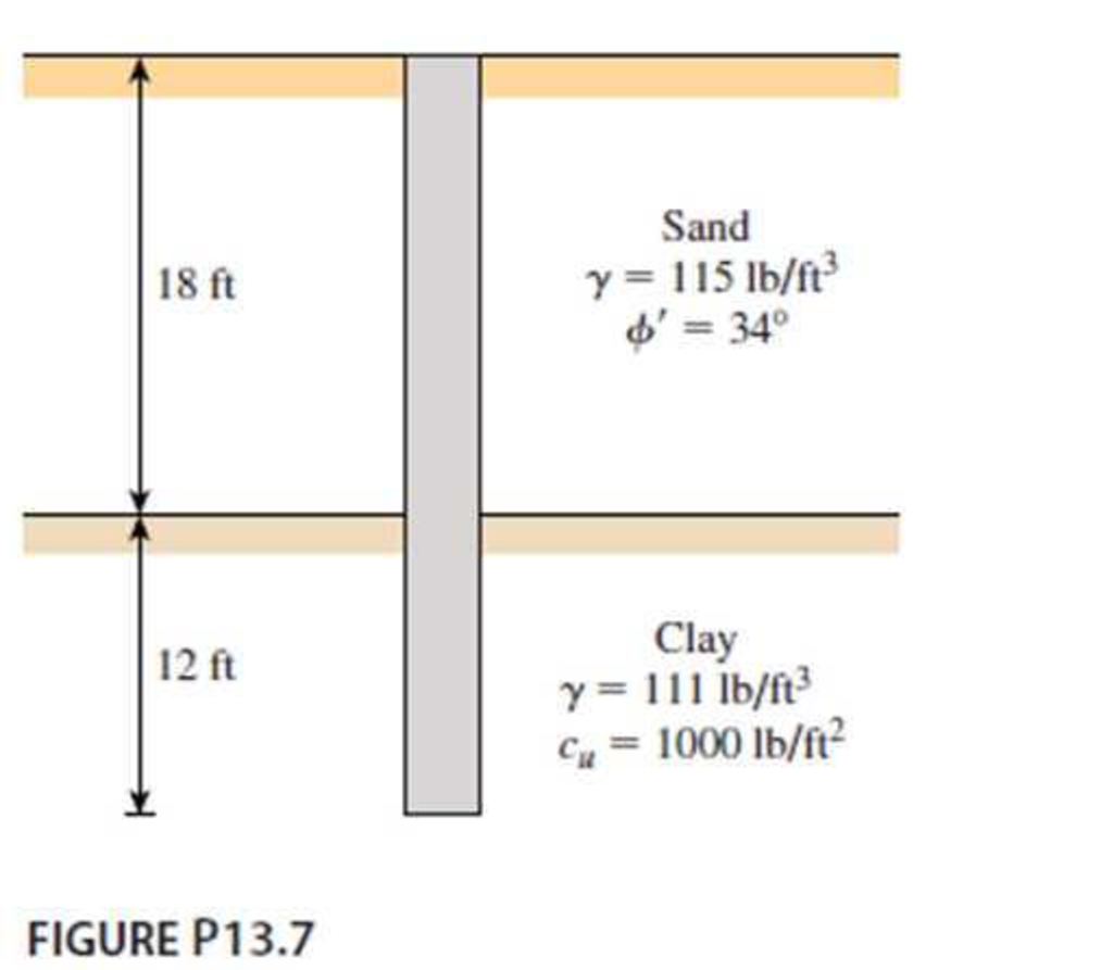
A 3 ft diameter straight drilled shaft is shown in Figure P13.7. Determine the load-carrying capacity of the drilled shaft with FS = 3. Take
Expert Solution & Answer

Trending nowThis is a popular solution!

Students have asked these similar questions
A free-headed drilled shaft, shown in Figure 4, has an elastic modulus, Ep = 20,000 MPa.
M, = 880 kN m
Q = 245 kN,
Sand
at = 19 kN/m3
O' = 34°
1.2 m
Figure 4
(a) Determine the ground line deflection, x.
Figure P10.7 shows a drilled shaft without a bell. Assume the following values:L1 = 6 m cu(1) = 50 kN/m2L2 = 7 m cu(2) = 75 kN/m2Ds = 1.5 mDetermine:a. The net ultimate point bearing capacity [use Eqs. (10.33) and (10.34)]b. The ultimate skin friction [use Eqs. (10.37) and (10.39)]c. The working load Qw (factor of safety = 3)
Refer to Figure 11.26b. For the drilled shaft with bell, given:Thickness of active zone, Z = 9 mDead load = 1500 kN Live load = 300 kNDiameter of the shaft, Ds = 1 mZero swell pressure for the clay in the active zone = 600 kN/m2Average angle of plinth-soil friction, Φ'ps = 20°Average undrained cohesion of the clay around the bell = 150 kN/m2. Determine the diameter of the bell, Db. A factor of safety of 3 against uplift is required with the assumption that dead load plus live load is equal to zero.
Chapter 13 Solutions
Principles of Foundation Engineering
Ch. 13 - Prob. 13.1PCh. 13 - Prob. 13.2PCh. 13 - Prob. 13.3PCh. 13 - Determine the ultimate load-carrying capacity of...Ch. 13 - For the same data given in Problem 13.4, determine...Ch. 13 - Prob. 13.6PCh. 13 - A 3 ft diameter straight drilled shaft is shown in...Ch. 13 - Prob. 13.8PCh. 13 - Figure P13.9 shows a drilled shaft extending into...Ch. 13 - A free-headed drilled shaft is shown in Figure...
Knowledge Booster


Learn more about
Need a deep-dive on the concept behind this application? Look no further. Learn more about this topic, civil-engineering and related others by exploring similar questions and additional content below.Similar questions
- A free-headed drilled shaft is shown in Figure P13.10. Let Qg = 260 kN, Mg = 0, = 17.5 kN/m3, = 35, c' = 0, and Ep = 22 106 kN/m2. Determine a. The ground line deflection, xo b. The maximum bending moment in the drilled shaft c. The maximum tensile stress in the shaft d. The minimum penetration of the shaft needed for this analysisarrow_forwardFigure P13.9 shows a drilled shaft extending into clay shale. Given: qu (clay shale) = 1.81 MN/m2. Considering the socket to be rough, estimate the allowable load-carrying capacity of the drilled shaft. Use FS = 4. Use the Zhang and Einstein procedure.arrow_forwardFor the drilled shaft described in Problem 19.7, estimate the total elastic settlement at working load. Use Eqs. (18.45), (18.47), and (18.48). Assume that Ep = 20 106 kN/m2, s = 0.3, Es = 12 103 kN/m2, = 0.65 and Cp = 0.03. Assume 80% mobilization of skin resistance at working load. (See Part c of Problem 19.7) 19.7 Figure 19.16 shows a drilled shaft without a bell. Here, L1 = 6 m, L2 = 7 m, Ds = 1.5 m, cu(1) = 50 kN/m2, and cu(2) = 75 kN/m2. Find these values: a. The net ultimate point bearing capacity. Use Eqs. (19.23) and (19.24) b. The ultimate skin resistance. Use Eqs. (19.26) and (19.28) c. The working load, Qw (FS = 3) FIG. 19.16arrow_forward
- Determine the ultimate load-carrying capacity of the drilled shaft shown in Figure P13.4, using the Reese and ONeill (1989) method.arrow_forwardFor the drilled shaft described in Problem 19.7, determine these values: a. The ultimate load-carrying capacity b. The load-carrying capacity for a settlement of 25 mm Use the procedure outlined in Section 19.8. 19.7 Figure 19.16 shows a drilled shaft without a bell. Here, L1 = 6 m, L2 = 7 m, Ds = 1.5 m, cu(1) = 50 kN/m2, and cu(2) = 75 kN/m2. Find these values: a. The net ultimate point bearing capacity. Use Eqs. (19.23) and (19.24) b. The ultimate skin resistance. Use Eqs. (19.26) and (19.28) c. The working load, Qw (FS = 3) FIG. 19.16arrow_forwardA drilled shaft constructed in medium sand is shown in the figure below. Given information is: y = 18 kN/m', '= 38°. Sand is medium-density sand, and the average standard penetration number (N60) within 2Ds below the drilled shaft is 19. Using the method proposed by Reese and O'Neill, determine the following: (a) The net allowable point resistance for a base movement of 25 mm. (b) The shaft frictional resistance for a base movement of 25 mm. (c) The total load that can be carried by the drilled shaft for a total base movement of 25 mm. 1 m 11 m 12 m - 2 marrow_forward
- A drilled shaft designed in accordance with the AASHTO code must support the following downward and uplift axial design loads: P = 850 k, Pup. = 270 k. The soil profile consists of: Undrained Shear Strength, s,, (lb/ft²) Depth (ft) Soil Description Unit Weight, y (lb/ft³) N60 0-15 Clayey silt 115 1200 15-35 Silty clay 112 1800 35-55 Sandy silt (nonplastic) 115 24 55-80 Silty sand 124 43 Practice Problems 597 The groundwater is at a depth of 50 ft. Using the AASHTO resistance factors, select a diameter and depth for a single drilled shaft to support these design loads. Use a load factor of 0.9 on the weight of the shaft. Note there are many different diameter-length combinations that would be satisfactory, but select one that you think would be most appropriate.arrow_forwardEarth Sciences Downward force is 4000 kg and rotational force is 3000 kg. Contact surface area (cross sectional area) is 100 cm2. Also, the rock sample (diameter: 20 cm) is tested by a uniaxial compressive strength machine and the sample was cracked at 30000 kg. Answer the following questions:a. Find the resultant force acting on the rock formation.b. Find the bearing strength of the rock drilled.c. Can we drill under these circumstances?arrow_forward1. Triaxial compression tests are done on quartzite rocks, the results are shown below. (0₁+03)/2 -964.25 14500 19575 23200 29000 43210 63075 psi (01-03)/2 964.25 14500 18850 21750 26100 35960 48575 psi Comment on the applicability of each of the Mohr-Coulomb, Griffith, and Hoek-Brown criteria for the testing results.arrow_forward
- Hint: The problem is 10.10 taken from the book " introductory to mining engineering " written by "Howard L.Hartman" A single rectangular opening 10 ft in height is driven in rock having strengths of fc=18000 lb/in2 and ft= 1500 lb/in2. Rock specific gravity is 2.3. The opening is located at a depth of 2000 ft in a stress field of no lateral pressure and has a fillet ratio of 1/6. (a). Determine if the opening will fail when its width is 20 ft ? (b). What is the maximum safe width of the opening?.A single rectangular opening 10 ft (3.0 m) in height is driven in rock having strengths of fc = 18,000 lb/in2 (124 MPa) and ft=1500 lb/in2. (10.3 MPa).Rock specific gravity is 2.3.The opening is located at depth of 2000 ft (610 m) in a stress field of no lateral pressure and has a fillet ratio of 1/6 .a. Determine if the opening will fail when its width is 20 ft (6.1 m).b. Is there any benefit to reducing the width to 10 ft (3.0 m)? To 5 ft (1.5 m)?c. What is the maximum safe width of opening?arrow_forwardA standard penetration test is carried out in sand where the efficiency of the hammer nH =70%. If the measured N-value at 30 ft depth is 24, find N60 and (N1)60. The unit weight of the sand is 115.0 lb/ft3. Assume nB = nS = nR =1.arrow_forward
arrow_back_ios
arrow_forward_ios
Recommended textbooks for you
 Principles of Foundation Engineering (MindTap Cou...Civil EngineeringISBN:9781337705028Author:Braja M. Das, Nagaratnam SivakuganPublisher:Cengage Learning
 Principles of Foundation Engineering (MindTap Cou...Civil EngineeringISBN:9781305081550Author:Braja M. DasPublisher:Cengage Learning
 Fundamentals of Geotechnical Engineering (MindTap...Civil EngineeringISBN:9781305635180Author:Braja M. Das, Nagaratnam SivakuganPublisher:Cengage Learning
Principles of Foundation Engineering (MindTap Cou...
Civil Engineering
ISBN:9781337705028
Author:Braja M. Das, Nagaratnam Sivakugan
Publisher:Cengage Learning
Principles of Foundation Engineering (MindTap Cou...
Civil Engineering
ISBN:9781305081550
Author:Braja M. Das
Publisher:Cengage Learning
Fundamentals of Geotechnical Engineering (MindTap...
Civil Engineering
ISBN:9781305635180
Author:Braja M. Das, Nagaratnam Sivakugan
Publisher:Cengage Learning
CE 414 Lecture 02: LRFD Load Combinations (2021.01.22); Author: Gregory Michaelson;https://www.youtube.com/watch?v=6npEyQ-2T5w;License: Standard Youtube License