
Videos
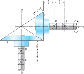
The figure shows a 10 diametral pitch 18-tooth 20° straight bevel pinion driving a 30-tooth gear. The transmitted load is 25 lbf. Find the bearing reactions at C and D on the output shaft if D is to take both radial and thrust loads.
Problem 13–44
Dimensions in inches.
The bearing reaction at
The bearing reaction at
Answer to Problem 44P
The bearing reaction at
The bearing reaction at
Explanation of Solution
The figure below shows the forces acting at the bevel gear and pinion assembly.
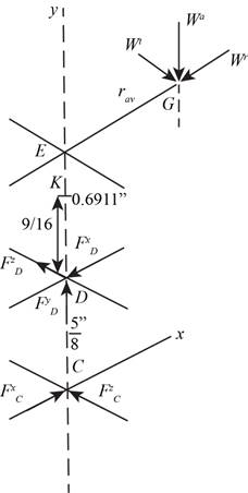
Figure-(1)
Write the expression for the diameter of gear 2.
Here, the diametrical pitch is
Write the expression for the diameter of gear 3.
Here, the number of teeth on gear 3 is
Write the expression for the pitch angle for gear 2.
Write the expression for the pitch angle for gear 3.
Write the expression fort the pitch radius at the mid-point of the bevel gear.
Here, the lateral side of the gear 2 is
Write the expression for
Here, the distance between the points
Write the expression for the radial load.
Here, the pressure angle is
Write the expression for the axial load.
Write the expression of the load in vector form.
Write the expression for the position vector of
Write the expression for the position vector of
Write the expression for the force on the bearing
Here, the force on bearing
Write the expression for the moment about
Here, the torque is
Write the expression for the force equilibrium for the set of bearings.
Substitute
Conclusion:
Substitute
Substitute
Substitute
Substitute
Substitute
Substitute
Substitute
Substitute
Substitute
Substitute
Compare the
Compare the
Compare the
Substitute
Thus, the bearing reaction at
Substitute
Thus, the bearing reaction at
Want to see more full solutions like this?
Chapter 13 Solutions
Loose Leaf for Shigley's Mechanical Engineering Design Format: LooseLeaf


- A Coniflex, straight-tooth bevel gearset is supported on shafts with centerlines intersecting at a 90° angle. The gear is straddle mounted between closely positioned bearings, and the pinion overhangs its support bearing. The 15-tooth pinion rotates at 900 rpm, driving the 60-tooth gear, which has a di- ametral pitch of 6, pressure angle of 20°, and face width of 1.25 inches. The material for both gears is through-hardened Grade I steel with a hardness of BHN 300 (see Figure). It is desired to have a reliability of 90 percent, a design life of 10° cy- cles, and a governing safety factor of 2.5. Estimate the maximum horsepower that can be transmitted by this gear re- ducer while meeting all of the design specifications given.arrow_forwardA pair of gray iron and steel helical gears, having a helix angle of 15° with 20° full-depth teeth are to transmit 10 hp at 1500 rpm of a 4-in pinion having a total number of 28teeth. The velocity ratio desired is about mw = 4. Find the (a) normal circular pitch, (b) normal diametral pitch, (c) axial pitch, and (d) dynamic loaarrow_forwardA parallel helical gear set of 19 tooth pinion is driving a 57 tooth gear. The helix angle of 20 degrees while the normal pressure angle is 14.5 degrees and the normal diametral pitch of 10 teeth/inch. If the pinion is rotating at 1800rpm and transmits 50hp, find the normal force. Please answer in detailed solution.arrow_forward
- A 57-tooth spur gear is in mesh with a 23-tooth pinion. The gearset transmits 125 hp at 1000 pinion rpm. Size the spur gears for a bending failure safety factor of at least 2 assuming a steady torque, 25∘ pressure angle, full-depth teeth, Qν = 9, an AISI 4140 steel pinion, and a class 40 cast iron gear. Part A Find the appropriate standard diametral pitch for the gearset. Part B Find the minimum required face width of the gears needed to satisfy the safety requirementsarrow_forwardA pair of gears with 20° full-depth teeth are to transmit 15hp at 1750 rpm of the 4-in pinion; velocity ratio desired is about mw= 4; intermittent service. Use a strength reduction factor of about 1.4, with the load at the tip and teeth carefullycut. A.Determine the diametral pitch, B. face width, C. and tooth numbers if the material is cast iron, class 25arrow_forwardIn a gear set, a 36-tooth spur pinion drives a 60-tooth spur gear. The teeth of these gear are cast iron profile. The diametral pitch is 6-teeth/in, the face width si 0.5 inches, and the pressure angle is 20 degrees. Assume that the pinion transmits 10 hp at a speed of 2000 rpm. Find the tangential load in lbf Find the contact stress in kpsi, assuming CP=1960 psi.arrow_forward
- A 17-tooth 20° pressure angle spur pinion rotates at 1800 rev/min and transmits 4 hp to a 52-tooth disk gear. The diametral pitch is 10 teeth/in, the face width 1.5 in, and the quality standard is No. 6. The gears are straddle-mounted with bearings immediately adjacent. The pinion is a grade 1 steel with a hardness of 240 Brinell tooth surface and through-hardened core. The gear is steel, through-hardened also, grade 1 material, with a Brinell hardness of 200, tooth surface and core. Poisson's ratio is 0.30, Jp = 0.30, JG = 0.40, and Young's modulus is 30(10°) psi. The loading is smooth because of motor and load. Assume a pinion life of 108 cycles and a reliability of 0.90, and use YN = 1.3558N-0.0178, ZN = 1.4488N-0.023. The tooth profile is uncrowned. This is a commercial enclosed gear unit. (a) Find the factor of safety of the gears in bending. (b) Find the factor of safety of the gears in wear. (c) By examining the factors of safety, identify the threat to each gear and to the…arrow_forward13-32 The 247 6-pitch 20° pinion 2 shown in the figure rotates clockwise at 1000 rev/min and is driven at a power of 25 hp. Gears 4, 5, and 6 have 24, 36, and 144 teeth, respectively. What torque can arm 3 deliver to its output shaft? Draw free-body diagrams of the arm and of each gear and show all forces that act upon them.arrow_forwardA steel shaft 800 mm long transmitting 15 kW at 400 r.p.m. is supported at two bearings at the twoends. A gear wheel having 80 teeth and 500 mm pitch circle diameter is mounted at 200 mm from theleft hand side bearing and receives power from a pinion meshing with it. The axis of pinion and gearlie in the horizontal plane. A pulley of 300 mm diameter is mounted at 200 mm from right hand sidebearing and is used for transmitting power by a belt. The belt drive is inclined at 30° to the vertical inthe forward direction. The belt lap angle is 180 degrees. The coefficient of friction between belt andpulley is 0.3. Design and sketch the arrangement of the shaft assuming the values of safe stresses as :τ = 55 MPa; σt= 80 MPa. Take torsion and bending factor 1.5 and 2 respectively.arrow_forward
- Please answer part 2, A 20° full depth involute spur pinion of 4 mm module and 21 teeth is to transmit 15 kW at 960 rpm. Its face width is 25 mm. 1.The tangential force transmitted (in N) is (a) 3552 (b) 2611 (c) 1776 (d) 1305 2. Given that the tooth geometry factor is 0.32 and the combined effect of dynamic load and allied factors intensifying the stress is 1.5 the minimum allowable stress for the gear material in MPa is, (a) 242.0 (c) 121.0 (b) 166.5 (d) 74.0arrow_forwardProvide very clear and complete solution and diagam. SITUATIONAL PROBLEM: Two shafts are connected by spur gears. The pitch radii of the gears A and B are 200 mm and 860 mm respectively. If shaft A makes 350rpm and is subjected to twisting moment of 250 N-m. Pressure angle is 14.5 degree. What is: a.) Rpm of gear B b.) Torque in shaft B (in Newton meter). c.) Separation load of two gears (in newtons). d.) Total load on gears (in newtons).arrow_forwardFor the gear mechanism in the figure: P1 = 4 kW, η1 = 1000 rpm, z1 = 18, z2 = 36, z3 = 54, z4 = 108, z1 is the driving gear. Total efficiency values for each stage; Since η12 = η34 = 0.96; Find the output torque and speed of gear z4.arrow_forward
 Elements Of ElectromagneticsMechanical EngineeringISBN:9780190698614Author:Sadiku, Matthew N. O.Publisher:Oxford University Press
 Mechanics of Materials (10th Edition)Mechanical EngineeringISBN:9780134319650Author:Russell C. HibbelerPublisher:PEARSON
 Thermodynamics: An Engineering ApproachMechanical EngineeringISBN:9781259822674Author:Yunus A. Cengel Dr., Michael A. BolesPublisher:McGraw-Hill Education
 Control Systems EngineeringMechanical EngineeringISBN:9781118170519Author:Norman S. NisePublisher:WILEY
 Mechanics of Materials (MindTap Course List)Mechanical EngineeringISBN:9781337093347Author:Barry J. Goodno, James M. GerePublisher:Cengage Learning
 Engineering Mechanics: StaticsMechanical EngineeringISBN:9781118807330Author:James L. Meriam, L. G. Kraige, J. N. BoltonPublisher:WILEY