
Loose Leaf for Engineering Circuit Analysis Format: Loose-leaf
9th Edition
ISBN: 9781259989452
Author: Hayt
Publisher: Mcgraw Hill Publishers
expand_more
expand_more
format_list_bulleted
Concept explainers
Videos
Textbook Question
Chapter 13.2, Problem 4P
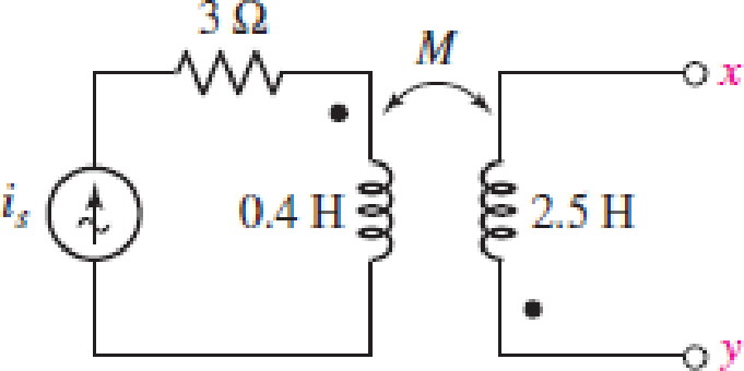
Let is = 2 cos 10t A in the circuit of Fig. 13.14, and find the total energy stored in the passive network at t = 0 if k = 0.6 and terminals x and y are (a) left open-circuited; (b) short-circuited.
FIGURE 13.14
Expert Solution & Answer
Want to see the full answer?
Check out a sample textbook solution
Students have asked these similar questions
Explore the challenges and benefits of implementing power electronics-based grid solutions like STATCOM (Static Synchronous Compensator) for voltage control and stability.
please solve A 10 kVA, 500/250 V, single phase transformer has itsmaximum efficiency of 94% when delivering 90% ofits rated output at unity p.t. Estimate its efficiency whendelivering its full load output at p.t. of 0.8 lagging.
An Electrical engineer is asked by a client to prepare a technical specification on specific items connected with a project.
Hence, the engineer is requested to prepare the technical specification of the following:
PROJECT: A Subdivision Development
Lot AREA; 2 Hectares
LOCATION: Brgy. Kanlurang Mayao, Lucna City
Technical specification of fuse cutout
Technical specification of transformer
Chapter 13 Solutions
Loose Leaf for Engineering Circuit Analysis Format: Loose-leaf
Ch. 13.1 - Assuming M = 10 H, coil L2 is open-circuited, and...Ch. 13.1 - For the circuit of Fig. 13.9, write appropriate...Ch. 13.1 - For the circuit of Fig. 13.11, write an...Ch. 13.2 - Let is = 2 cos 10t A in the circuit of Fig. 13.14,...Ch. 13.3 - Element values for a certain linear transformer...Ch. 13.3 - (a) If the two networks shown in Fig. 13.20 are...Ch. 13.3 - If the networks in Fig. 13.23 are equivalent,...Ch. 13.4 - Prob. 8PCh. 13.4 - Let N1 = 1000 turns and N2 = 5000 turns in the...Ch. 13 - Prob. 1E
Ch. 13 - With respect to Fig. 13.36, assume L1 = 500 mH, L2...Ch. 13 - The circuit in Fig. 13.36 has a sinusoidal input...Ch. 13 - Prob. 4ECh. 13 - Prob. 5ECh. 13 - The circuit in Fig. 13.38 has a sinusoidal input...Ch. 13 - The physical construction of three pairs of...Ch. 13 - Prob. 8ECh. 13 - Prob. 9ECh. 13 - Calculate v1 and v2 if i1 = 5 sin 40t mA and i2 =...Ch. 13 - Prob. 11ECh. 13 - For the circuit of Fig. 13.41, calculate I1, I2,...Ch. 13 - Prob. 13ECh. 13 - Prob. 14ECh. 13 - In the circuit of Fig. 13.43, M is reduced by an...Ch. 13 - Prob. 16ECh. 13 - Prob. 17ECh. 13 - Prob. 18ECh. 13 - Prob. 19ECh. 13 - Note that there is no mutual coupling between the...Ch. 13 - Prob. 21ECh. 13 - (a) Find Zin(j) for the network of Fig 13.50. (b)...Ch. 13 - For the coupled coils of Fig. 13.51, L1 = L2 = 10...Ch. 13 - Prob. 24ECh. 13 - Prob. 25ECh. 13 - Prob. 26ECh. 13 - Consider the circuit represented in Fig. 13.53....Ch. 13 - Compute v1, v2, and the average power delivered to...Ch. 13 - Assume the following values for the circuit...Ch. 13 - Prob. 30ECh. 13 - Prob. 31ECh. 13 - Prob. 32ECh. 13 - Prob. 33ECh. 13 - Prob. 34ECh. 13 - Prob. 35ECh. 13 - Prob. 36ECh. 13 - Prob. 37ECh. 13 - FIGURE 13.60 For the circuit of Fig. 13.60, redraw...Ch. 13 - Prob. 39ECh. 13 - Prob. 40ECh. 13 - Calculate the average power delivered to the 400 m...Ch. 13 - Prob. 42ECh. 13 - Calculate the average power delivered to each...Ch. 13 - Prob. 44ECh. 13 - Prob. 45ECh. 13 - Prob. 46ECh. 13 - Prob. 47ECh. 13 - Prob. 48ECh. 13 - A transformer whose nameplate reads 2300/230 V, 25...Ch. 13 - Prob. 52ECh. 13 - As the lead singer in the local rock band, you...Ch. 13 - Obtain an expression for V2/Vs in the circuit of...Ch. 13 - Prob. 55E
Additional Engineering Textbook Solutions
Find more solutions based on key concepts
Analog Voltmeter Design Figure P2-98(a) shows a voltmeter circuit consisting of a D'Arsonval meter, two series ...
ANALYSIS+DESIGN OF LINEAR CIRCUITS(LL)
The current source in the circuit shown generates the current pulse
Find (a) v (0); (b) the instant of time gr...
Electric Circuits. (11th Edition)
Assume a telephone signal travels through a cable at two-thirds the speed of light. How long does it take the s...
Electric Circuits (10th Edition)
Electric power systems provide energy in a variety of commercial and industrial settings. Make a list of system...
Principles and Applications of Electrical Engineering
Does the severity of an electric shock increase ordecrease with eh of the following changes? a. A decrease in t...
Electric Motors and Control Systems
Identify the type of input and output configuration for each diff-amp in Figure 18-35.
Electronics Fundamentals: Circuits, Devices & Applications
Knowledge Booster


Learn more about
Need a deep-dive on the concept behind this application? Look no further. Learn more about this topic, electrical-engineering and related others by exploring similar questions and additional content below.Similar questions
- DESIGN A CONVENTIONAL POWER SUPPLY USING 220V AC , 10 KILO OHMS RESISTOR ,4 SILICON DIODES, CAPACITOR , TRANSFORMER WITH 20:1 TURNS' RATIO AND PERCENTAGE ERROR= 5 PERCENT. FIND THE SUITABLE REGULATORarrow_forwardGiven a 115kV/13.2kV distribution transformer rated at 30MVA with an 8% nameplate impedance what is the full Load current in ampsarrow_forward"A single coil 800 turns instrument transformer, operating in the step-downs mode with a 25 percent tap, supplies a 10 kVA, 0.80 power factor lagging load. The input to the transformer is 6600 V, 50 Hz. Assume that leakage effects and minor losses in transformer are negligible. Determine the following : (i) Turn ratio; (ii) Load current(in Amp); (iii) Incoming line current(in Amp); (iv) Transformed current (in Amp); (v) Apparent power conducted(in kVA)and (vi) Apparent power transformed"arrow_forward
- single coil 600 turns instrument transformer, operating in the step-down mode with a 40 percent tap, supplies a 5 kVA, 0.88 power factor inductive load. The input to the transformer is 3.3 kV, 50 Hz. Assume that leakage effects and minor losses in transformer are negligible. Determine the following : (0) Turn ratio; (ii) Load current(in Amp); (iii) Incoming line current(in Amp); (iv) Transformed current (in Amp); (v) Apparent power conducted(in kVA)and (vi) Apparent power transformed"arrow_forwardYou are tasked to design a dc power supply that operates from a single-phase ac supply (50Hz) with source inductanceof 1.5mH/phase. It is required to supply a dc load (resistive) with 55A at 322 Volt. Assume infinite inductive filtering andthe use of power diodes with a forward voltdrop of 0.7V. Consider the bridge converter topology and specify the followingdesign parameters,30) the loss in voltage due to commutation overlap;31) the r.m.s. ac supply voltage required;32) the overlap angle;33) the transformer utilisation factor;34) the rectification efficiency of the converter;35) the dc current rating of the rectifier diodes;36) the r.m.s. current rating of the rectifier diodes;37) the form factor of the diode current;38) the peak repetitive forward current rating of the rectifier diodes;39) the peak repetitive reverse voltage rating of the rectifier diodes.arrow_forwardA 10 kVA, 500/250 V, single phase transformer has its maximum efficiency of 94% when delivering 90% of its rated output at unity p.t. Estimate its efficiency when delivering its full load output at p.t. of 0.8 lagging.3arrow_forward
- The mutual inductance and self-inductances of the coils shown are M=40 mH, L1=25 mH, and L2=100 mH. 1. Calculate the coupling coefficient. 2. Calculate the energy stored in the coupled coils when i1=10 A and i2=15 A 3. If the coupling coefficient is increased to 1 and i1=10 A, what value of i2 results in zero stored energy?arrow_forwardWe want to build an impedance matching transformer that matches the output impedance of an amplifier connected to the primary, with a number of turns Np, whose impedance is 600 Ω, with an 8Ω speaker connected to the secondary, with a number of turns Ns. The Np/Ns transformation ratio of the matcher is: answer:8,66arrow_forwardPlease Solve ASPS. A 100 kVA, 2000/400 V, 50 Hz, single phase shell type transformer has sandwitch coils. There are two full HIV coils, one full LV coil and two half LV colls. Calculate the value of leakage reactance referred to HV side if the other data given is, depth of HV coil = 4 cm depth of LV coil = 3.6 cm depth of duct between IIV and LV= 1.6 cm width of winding 12 cm length of mean turns = 150 cm HV winding turns = 200 Also calculate the per unit reactance.arrow_forward
- Nominal tests 50 kVA, 20,000 / 480 V, 60 Equivalent of single phase transformer in Hz to determine circuit parameters Table of data for experiments presented. a. Obtain the T-equivalent circuit of the transformer reduced to secondary. b. Calculate the efficiency of the loaded transformer with 0.7-inductive power factor at the label current. c. The transformer is connected to the 50 Hz network and 0.7-inductive power factor at the tag current loaded with. Calculate the efficiency of the transformer.arrow_forwardA 10 kVA, 500/250 V, single phase transformer has its maximum efficiency of 94% when delivering 90% of its rated output at unity p.t. Estimate its efficiency when delivering its full load output at p.t. of 0.8 lagging,arrow_forwardA 2.4-kVA, 2400/240-V, 50-Hz, step-down transformer has the followingparameters: R, = 1.5 a, X, = 2.5 R, R, = 0.02 a, X, = 0.03 Q, R,, = 6 kR,and X,, = 8 kR. It is operating at 80% of its load at unity power factor.Using the exact equivalent circuit embodying the ideal transformer, determine the efficiency of the transformer. Also sketch its phasor diagram.arrow_forward
arrow_back_ios
SEE MORE QUESTIONS
arrow_forward_ios
Recommended textbooks for you
 Introductory Circuit Analysis (13th Edition)Electrical EngineeringISBN:9780133923605Author:Robert L. BoylestadPublisher:PEARSON
 Delmar's Standard Textbook Of ElectricityElectrical EngineeringISBN:9781337900348Author:Stephen L. HermanPublisher:Cengage Learning
 Programmable Logic ControllersElectrical EngineeringISBN:9780073373843Author:Frank D. PetruzellaPublisher:McGraw-Hill Education
 Fundamentals of Electric CircuitsElectrical EngineeringISBN:9780078028229Author:Charles K Alexander, Matthew SadikuPublisher:McGraw-Hill Education
 Electric Circuits. (11th Edition)Electrical EngineeringISBN:9780134746968Author:James W. Nilsson, Susan RiedelPublisher:PEARSON
 Engineering ElectromagneticsElectrical EngineeringISBN:9780078028151Author:Hayt, William H. (william Hart), Jr, BUCK, John A.Publisher:Mcgraw-hill Education,
Introductory Circuit Analysis (13th Edition)
Electrical Engineering
ISBN:9780133923605
Author:Robert L. Boylestad
Publisher:PEARSON
Delmar's Standard Textbook Of Electricity
Electrical Engineering
ISBN:9781337900348
Author:Stephen L. Herman
Publisher:Cengage Learning
Programmable Logic Controllers
Electrical Engineering
ISBN:9780073373843
Author:Frank D. Petruzella
Publisher:McGraw-Hill Education
Fundamentals of Electric Circuits
Electrical Engineering
ISBN:9780078028229
Author:Charles K Alexander, Matthew Sadiku
Publisher:McGraw-Hill Education
Electric Circuits. (11th Edition)
Electrical Engineering
ISBN:9780134746968
Author:James W. Nilsson, Susan Riedel
Publisher:PEARSON
Engineering Electromagnetics
Electrical Engineering
ISBN:9780078028151
Author:Hayt, William H. (william Hart), Jr, BUCK, John A.
Publisher:Mcgraw-hill Education,
Current Divider Rule; Author: Neso Academy;https://www.youtube.com/watch?v=hRU1mKWUehY;License: Standard YouTube License, CC-BY