
Vector Mechanics for Engineers: Statics and Dynamics
12th Edition
ISBN: 9781259638091
Author: Ferdinand P. Beer, E. Russell Johnston Jr., David Mazurek, Phillip J. Cornwell, Brian Self
Publisher: McGraw-Hill Education
expand_more
expand_more
format_list_bulleted
Concept explainers
Videos
Textbook Question
Chapter 15.1, Problem 15.34P
Two friction disks A and B are to be brought into contact without slipping when the angular velocity of disk A is 240 rpm counterclockwise. Disk A starts from rest at time t = 0 and is given a constant angular acceleration with a magnitude α. Disk B starts from rest at time t = 2 s and is given a constant clockwise angular acceleration, also with a magnitude α. Determine (a) the required angular acceleration magnitude α, (b) the time at which the contact occurs.
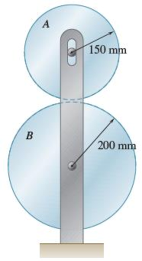
Fig. P15.34 and P15.35
Expert Solution & Answer
Want to see the full answer?
Check out a sample textbook solution
Students have asked these similar questions
Two friction disks A and B are to be brought into contact without slipping when the angular velocity of disk A is 240 rpm counterclockwise. Disk A starts from rest at time t= 0 and is given a constant angular acceleration with a magnitude a. Disk B starts from rest at time t= 2 s and is given a constant clockwise angular acceleration, also with a magnitude a. Determine (a) the required angular acceleration magnitude a, (b) the time at which the contact occurs.
Two friction wheels A and B are both rotating freely at 300 rpm counterclockwise when they are brought into contact. After 12 s of slippage, during which time each wheel has a constant angular acceleration, wheel B reaches a final angular velocity of 75 rpm counterclockwise. Determine (a) the angular acceleration of each wheel during the period of slippage, (b) the time at which the angular velocity of wheel A is equal to zero.
A simple friction drive consists of two disks A and B . Initially, disk B has a clockwise angular velocity of 500 rpm, and disk A is at rest. It is known that disk B will coast to rest in 60 s. However, rather than waiting until both disks are at rest to bring them together, disk A is given a constant angular acceleration of 3 rad/s2 counterclockwise. Determine (a) at what time the disks can be brought together if they are not to slip, (b) the angular velocity of each disk as contact is made.
Chapter 15 Solutions
Vector Mechanics for Engineers: Statics and Dynamics
Ch. 15.1 - A rectangular plate swings from arms of equal...Ch. 15.1 - Knowing that wheel A rotates with a constant...Ch. 15.1 - The brake drum is attached to a larger flywheel...Ch. 15.1 - The motion of an oscillating flywheel is defined...Ch. 15.1 - The motion of an oscillating flywheel is defined...Ch. 15.1 - As steam is slowly injected into a turbine, the...Ch. 15.1 - A small grinding wheel is attached to the shaft of...Ch. 15.1 - A connecting rod is supported by a knife-edge at...Ch. 15.1 - Prob. 15.7PCh. 15.1 - The angular acceleration of an oscillating disk is...
Ch. 15.1 - The angular acceleration of a shaft is defined by...Ch. 15.1 - The assembly shown consists of two rods and a...Ch. 15.1 - In Prob. 15.10, determine the velocity and...Ch. 15.1 - Prob. 15.12PCh. 15.1 - The rectangular block shown rotates about the...Ch. 15.1 - A circular plate of 120-mm radius is supported by...Ch. 15.1 - Prob. 15.15PCh. 15.1 - Prob. 15.16PCh. 15.1 - The earth makes one complete revolution on its...Ch. 15.1 - The sprocket wheel and chain shown are initially...Ch. 15.1 - Prob. 15.19PCh. 15.1 - Prob. 15.20PCh. 15.1 - The rated speed of drum B of the belt sander shown...Ch. 15.1 - The two pulleys shown may be operated with the V...Ch. 15.1 - A cyclist uses a stationary trainer during the...Ch. 15.1 - A gear reduction system consists of three gears A,...Ch. 15.1 - A belt is pulled to the right between cylinders A...Ch. 15.1 - Prob. 15.26PCh. 15.1 - Prob. 15.27PCh. 15.1 - A plastic film moves over two drums. During a 4-s...Ch. 15.1 - Cylinder A is moving downward with a velocity of 3...Ch. 15.1 - The system shown is held at rest by the...Ch. 15.1 - A load is to be raised 20 ft by the hoisting...Ch. 15.1 - A simple friction drive consists of two disks A...Ch. 15.1 - Prob. 15.33PCh. 15.1 - Two friction disks A and B are to be brought into...Ch. 15.1 - Two friction disks A and B are brought into...Ch. 15.1 - Steel tape is being wound onto a spool that...Ch. 15.1 - In a continuous printing process, paper is drawn...Ch. 15.2 - The ball rolls without slipping on the fixed...Ch. 15.2 - Three uniform rodsABC, DCE, and FGHare connected...Ch. 15.2 - Prob. 15.38PCh. 15.2 - An overhead door is guided by wheels at A and B...Ch. 15.2 - A painter is halfway up a 10-m ladder when the...Ch. 15.2 - Rod AB can slide freely along the floor and the...Ch. 15.2 - Rod AB can slide freely along the floor and the...Ch. 15.2 - Rod AB moves over a small wheel at C while end A...Ch. 15.2 - The disk shown moves in the xy plane. Knowing that...Ch. 15.2 - The disk shown moves in the xy plane. Knowing that...Ch. 15.2 - Prob. 15.46PCh. 15.2 - Velocity sensors are placed on a satellite that is...Ch. 15.2 - In the planetary gear system shown, the radius of...Ch. 15.2 - Prob. 15.49PCh. 15.2 - The outer gear C rotates with an angular velocity...Ch. 15.2 - Prob. 15.51PCh. 15.2 - A simplified gear system for a mechanical watch is...Ch. 15.2 - 15.53 and 15.54Arm ACB rotates about point C with...Ch. 15.2 - 15.53 and 15.54Arm ACB rotates about point C with...Ch. 15.2 - Knowing that at the instant shown the angular...Ch. 15.2 - Knowing that at the instant shown the velocity of...Ch. 15.2 - Knowing that the disk has a constant angular...Ch. 15.2 - The disk has a constant angular velocity of 20...Ch. 15.2 - The test rig shown was developed to perform...Ch. 15.2 - Prob. 15.60PCh. 15.2 - In the engine system shown, l = 160 mm and b = 60...Ch. 15.2 - In the engine system shown, l = 160 mm and b = 60...Ch. 15.2 - Knowing that the angular velocity of rod DE is a...Ch. 15.2 - In the position shown, bar AB has an angular...Ch. 15.2 - Prob. 15.65PCh. 15.2 - Prob. 15.66PCh. 15.2 - Prob. 15.67PCh. 15.2 - Prob. 15.68PCh. 15.2 - For the oil pump rig shown, link AB causes the...Ch. 15.2 - Both 6-in.-radius wheels roll without slipping on...Ch. 15.2 - The 80-mm-radius wheel shown rolls to the left...Ch. 15.2 - For the gearing shown, derive an expression for...Ch. 15.3 - The disk rolls without sliding on the fixed...Ch. 15.3 - Prob. 15.6CQCh. 15.3 - A juggling club is thrown vertically into the air....Ch. 15.3 - At the instant shown during deceleration, the...Ch. 15.3 - A helicopter moves horizontally in the x direction...Ch. 15.3 - Prob. 15.76PCh. 15.3 - Prob. 15.77PCh. 15.3 - Prob. 15.78PCh. 15.3 - In order to uncoil electrical wire from a spool...Ch. 15.3 - The arm ABC rotates with an angular velocity of 4...Ch. 15.3 - The double gear rolls on the stationary left rack...Ch. 15.3 - Prob. 15.82PCh. 15.3 - Rod ABD is guided by wheels at A and B that roll...Ch. 15.3 - Knowing that at the instant shown the angular...Ch. 15.3 - Knowing that at the instant shown the velocity of...Ch. 15.3 - A motor at O drives the windshield wiper mechanism...Ch. 15.3 - Prob. 15.88PCh. 15.3 - Small wheels have been attached to the ends of bar...Ch. 15.3 - Prob. 15.90PCh. 15.3 - The disk is released from rest and rolls down the...Ch. 15.3 - Prob. 15.92PCh. 15.3 - Two identical rods ABF and DBE are connected by a...Ch. 15.3 - Arm ABD is connected by pins to a collar at B and...Ch. 15.3 - Two rods ABD and DE are connected to three collars...Ch. 15.3 - Two 500-mm rods are pin-connected at D as shown....Ch. 15.3 - At the instant shown, the velocity of collar A is...Ch. 15.3 - Prob. 15.98PCh. 15.3 - Describe the space centrode and the body centrode...Ch. 15.3 - Describe the space centrode and the body centrode...Ch. 15.3 - Prob. 15.101PCh. 15.3 - Using the method of Sec. 15.3, solve Prob. 15.64....Ch. 15.3 - Using the method of Sec. 15.3, solve Prob. 15.65....Ch. 15.3 - Using the method of Sec. 15.3, solve Prob. 15.38....Ch. 15.4 - A rear-wheel-drive car starts from rest and...Ch. 15.4 - Fig. P15.105 and P15.106 15.105A 5-m steel beam is...Ch. 15.4 - For a 5-m steel beam AE, the acceleration of point...Ch. 15.4 - A 900-mm rod rests on a horizontal table. A force...Ch. 15.4 - In Prob. 15.107, determine the point of the rod...Ch. 15.4 - Knowing that point A is moving to the right at a...Ch. 15.4 - Knowing that at the instant shown crank BC has a...Ch. 15.4 - An automobile travels to the left at a constant...Ch. 15.4 - The 18-in.-radius flywheel is rigidly attached to...Ch. 15.4 - 15.113 and 15.114A 3-in.-radius drum is rigidly...Ch. 15.4 - 15.113 and 15.114A 3-in.-radius drum is rigidly...Ch. 15.4 - A heavy crate is being moved a short distance...Ch. 15.4 - Prob. 15.116PCh. 15.4 - The 100-mm-radius drum rolls without slipping on a...Ch. 15.4 - In the planetary gear system shown, the radius of...Ch. 15.4 - The 200-mm-radius disk rolls without sliding on...Ch. 15.4 - Knowing that crank AB rotates about point A with a...Ch. 15.4 - Knowing that crank AB rotates about point A with a...Ch. 15.4 - In the two-cylinder air compressor shown, the...Ch. 15.4 - The right leg of an athlete on a rowing machine...Ch. 15.4 - Arm AB has a constant angular velocity of 16 rad/s...Ch. 15.4 - Arm AB has a constant angular velocity of 16 rad/s...Ch. 15.4 - A straight rack rests on a gear of radius r = 3...Ch. 15.4 - The elliptical exercise machine has fixed axes of...Ch. 15.4 - The elliptical exercise machine has fixed axes of...Ch. 15.4 - Knowing that the angular velocity of rod DE is a...Ch. 15.4 - Knowing that at the instant shown bar DE has an...Ch. 15.4 - 15.131 and 15.132Knowing that at the instant shown...Ch. 15.4 - 15.131 and 15.132Knowing that at the instant shown...Ch. 15.4 - 15.133 and 15.134Knowing that at the instant shown...Ch. 15.4 - 15.133 and 15.134Knowing that at the instant shown...Ch. 15.4 - Prob. 15.135PCh. 15.4 - For the oil pump rig shown, link AB causes the...Ch. 15.4 - Denoting by rA the position vector of a point A of...Ch. 15.4 - Prob. 15.138PCh. 15.4 - Prob. 15.139PCh. 15.4 - Prob. 15.140PCh. 15.4 - Prob. 15.141PCh. 15.4 - Prob. 15.142PCh. 15.4 - Prob. 15.143PCh. 15.4 - Crank AB rotates with a constant clockwise angular...Ch. 15.4 - Crank AB rotates with a constant clockwise angular...Ch. 15.4 - Solve the engine system from Sample Prob. 15.15...Ch. 15.4 - Prob. 15.147PCh. 15.4 - Prob. 15.148PCh. 15.4 - Prob. 15.149PCh. 15.5 - A person walks radially inward on a platform that...Ch. 15.5 - The motion of pin P is guided by slots cut in rods...Ch. 15.5 - The motion of pin P is guided by slots cut in rods...Ch. 15.5 - 15.152 and 15.153Two rotating rods are connected...Ch. 15.5 - 15.152 and 15.153Two rotating rods are connected...Ch. 15.5 - Pin P is attached to the wheel shown and slides in...Ch. 15.5 - Knowing that at the instant shown the angular...Ch. 15.5 - Prob. 15.156PCh. 15.5 - The motion of pin P is guided by slots cut in rods...Ch. 15.5 - Prob. 15.158PCh. 15.5 - Prob. 15.159PCh. 15.5 - Prob. 15.160PCh. 15.5 - Pin P is attached to the collar shown; the motion...Ch. 15.5 - Prob. 15.162PCh. 15.5 - Prob. 15.163PCh. 15.5 - At the instant shown, the length of the boom AB is...Ch. 15.5 - At the instant shown, the length of the boom AB is...Ch. 15.5 - Prob. 15.166PCh. 15.5 - Prob. 15.167PCh. 15.5 - Prob. 15.168PCh. 15.5 - 15.168 and 15.169A chain is looped around two...Ch. 15.5 - Prob. 15.170PCh. 15.5 - Prob. 15.171PCh. 15.5 - The collar P slides outward at a constant relative...Ch. 15.5 - Pin P slides in a circular slot cut in the plate...Ch. 15.5 - Prob. 15.174PCh. 15.5 - Prob. 15.175PCh. 15.5 - Knowing that at the instant shown the rod attached...Ch. 15.5 - Prob. 15.177PCh. 15.5 - In Prob. 15.177, determine the angular velocity...Ch. 15.5 - At the instant shown, bar BC has an angular...Ch. 15.5 - Prob. 15.180PCh. 15.5 - Rod AB passes through a collar that is welded to...Ch. 15.5 - Prob. 15.182PCh. 15.5 - Prob. 15.183PCh. 15.6 - The bowling ball shown rolls without slipping on...Ch. 15.6 - Prob. 15.185PCh. 15.6 - Prob. 15.186PCh. 15.6 - Prob. 15.187PCh. 15.6 - The rotor of an electric motor rotates at the...Ch. 15.6 - Prob. 15.189PCh. 15.6 - Prob. 15.190PCh. 15.6 - In the system shown, disk A is free to rotate...Ch. 15.6 - Prob. 15.192PCh. 15.6 - Prob. 15.193PCh. 15.6 - A radar system is used to track a new experimental...Ch. 15.6 - A 3-in.-radius disk spins at the constant rate 2 =...Ch. 15.6 - Prob. 15.196PCh. 15.6 - The cone shown rolls on the zx plane with its apex...Ch. 15.6 - At the instant shown, the robotic arm ABC is being...Ch. 15.6 - Prob. 15.199PCh. 15.6 - Prob. 15.200PCh. 15.6 - Several rods are brazed together to form the...Ch. 15.6 - In Prob. 15.201, the speed of point B is known to...Ch. 15.6 - Prob. 15.203PCh. 15.6 - Prob. 15.204PCh. 15.6 - Rod BC and BD are each 840 mm long and are...Ch. 15.6 - Rod AB is connected by ball-and-socket joints to...Ch. 15.6 - Prob. 15.207PCh. 15.6 - Prob. 15.208PCh. 15.6 - Prob. 15.209PCh. 15.6 - Prob. 15.210PCh. 15.6 - Prob. 15.211PCh. 15.6 - Prob. 15.212PCh. 15.6 - Prob. 15.213PCh. 15.6 - Prob. 15.214PCh. 15.6 - In Prob. 15.205, determine the acceleration of...Ch. 15.6 - In Prob. 15.206, determine the acceleration of...Ch. 15.6 - In Prob. 15.207, determine the acceleration of...Ch. 15.6 - Prob. 15.218PCh. 15.6 - Prob. 15.219PCh. 15.7 - A flight simulator is used to train pilots on how...Ch. 15.7 - A flight simulator is used to train pilots on how...Ch. 15.7 - Prob. 15.222PCh. 15.7 - Prob. 15.223PCh. 15.7 - Prob. 15.224PCh. 15.7 - The bent rod shown rotates at the constant rate of...Ch. 15.7 - The bent pipe shown rotates at the constant rate 1...Ch. 15.7 - The circular plate shown rotates about its...Ch. 15.7 - Prob. 15.228PCh. 15.7 - Prob. 15.229PCh. 15.7 - Prob. 15.230PCh. 15.7 - Prob. 15.231PCh. 15.7 - Using the method of Sec. 15.7A, solve Prob....Ch. 15.7 - Prob. 15.233PCh. 15.7 - Prob. 15.234PCh. 15.7 - Prob. 15.235PCh. 15.7 - The arm AB of length 16 ft is used to provide an...Ch. 15.7 - The remote manipulator system (RMS) shown is used...Ch. 15.7 - A disk with a radius of 120 mm rotates at the...Ch. 15.7 - Prob. 15.239PCh. 15.7 - Prob. 15.240PCh. 15.7 - Prob. 15.241PCh. 15.7 - The cylinder shown rotates at the constant rate 2...Ch. 15.7 - Prob. 15.243PCh. 15.7 - Prob. 15.244PCh. 15.7 - Prob. 15.245PCh. 15.7 - Prob. 15.246PCh. 15.7 - Prob. 15.247PCh. 15 - A wheel moves in the xy plane in such a way that...Ch. 15 - Two blocks and a pulley are connected by...Ch. 15 - A baseball pitching machine is designed to deliver...Ch. 15 - The flywheel OD on the elliptical machine analyzed...Ch. 15 - The roller at point A on the elliptical machine...Ch. 15 - Knowing that at the instant shown rod AB has zero...Ch. 15 - Rod AB is attached to a collar at A and is fitted...Ch. 15 - Prob. 15.255RPCh. 15 - A disk of 0.15-m radius rotates at the constant...Ch. 15 - Prob. 15.257RPCh. 15 - Prob. 15.258RPCh. 15 - In the position shown, the thin rod moves at a...
Knowledge Booster


Learn more about
Need a deep-dive on the concept behind this application? Look no further. Learn more about this topic, mechanical-engineering and related others by exploring similar questions and additional content below.Similar questions
- In the design of a timing mechanism, the motion of pin P in the fixed circular slot is controlled by the guide A, which is being elevated by its lead screw. Guide A starts from rest with pin P at the lowest point in the circular slot, and accelerates upward at a constant rate until it reaches a speed of 130 mm/s at the halfway point of its vertical displacement. The guide then decelerates at a constant rate and comes to a stop with pin P at the uppermost point in the circular slot. Determine the n- and t-components of acceleration of pin P once the pin has traveled 29° around the slot from the starting position. Please solve step by steparrow_forwardIn the design of a timing mechanism, the motion of pin P in the fixed circular slot is controlled by the guide A, which is being elevated by its lead screw. Guide A starts from rest with pin P at the lowest point in the circular slot, and accelerates upward at a constant rate until it reaches a speed of 90 mm/s at the halfway point of its vertical displacement. The guide then decelerates at a constant rate and comes to a stop with pin P at the uppermost point in the circular slot. Determine the n- and t-components of acceleration of pin P once the pin has traveled 23° around the slot from the starting position.arrow_forwardTwo identical giant flywheels are on 2 identical slopes at an angle alpha = 20 deg. One flywheel is rolling on its inside shaft of diameter d1 = 3 ft, and the second flywheel is rolling without slipping on its outside diameter d2 = 5 ft. They are both released from rest. The weight of the flywheel is W = 8 lbs 1. Knowing that flywheel 1 attains a speed of v = 7.0 ft/s in t = [t] s, (if t doesn't show take any t between 5 and 10 sec) find the radius of gyration of the flywheels, following those steps: 3. What will be the distance between the 2 flywheels? Which one is in front? a. Explain your strategy to find the distance made by each wheel. b. Find the 3 distances made by each wheel. c. Find the distance between the 2 flywheels. d. Why one is in front? 4. Using flywheel 2, what is the coefficient of static friction between the outside diameter and the ground required to prevent slipping? a. Using the 3 previous diagrams, which impulse will you consider finding the force of…arrow_forward
- Cylinder A is moving downward with a velocity of 3 m/s when the brake is suddenly applied to the drum. Knowing that the cylinder moves 6 m downward before coming to rest and assuming uniformly accelerated motion, determine (a) the angular acceleration of the drum, (b) the time required for the cylinder to come to rest.arrow_forwardTwo identical giant flywheels are on 2 identical slopes at an angle alpha = 20 deg. One flywheel is rolling on its inside shaft of diameter d1 = 3 ft, and the second flywheel is rolling without slipping on its outside diameter d2 = 5 ft. They are both released from rest. The weight of the flywheel is W = 8 lbs Knowing that flywheel 1 attains a speed of v = 7.0 ft/s in t = [t] s, (if t doesn't show take any t between 5 and 10 sec) find the radius of gyration of the flywheels, following those steps: b. Find omega final c. Find the angular impulse at the point of contact between the shaft and the slope. d. Write the formula to find the final momentum. e. Solve for k, using the principle of angular impulse and momentumarrow_forwardTwo friction disks A and B are brought into contact when the angular velocity of disk A is 240 rpm counterclockwise and disk B is at rest. A period of slipping follows and disk B makes two revolutions before reaching its final angular velocity. Assuming that the angular acceleration of each disk is constant and inversely proportional to the cube of its radius, determine (a) the angular acceleration of each disk, (b) the time during which the disks slip.arrow_forward
- A small grinding wheel is attached to the shaft of an electric motor which has a rated speed of 3600 rpm. When the power is turned on, the unit reaches its rated speed in 5 s, and when the power is turned off, the unit coasts to rest in 70 s. Assuming uniformly accelerated motion, determine the number of revolutions that the motor executes (a) in reaching its rated speed, (b) in coasting to rest.arrow_forwardA 1.8-kg collar A and a 0.7-kg collar B can slide without friction on a frame, consisting of the horizontal rod OE and the vertical rod CD, which is free to rotate about its vertical axis of symmetry. The two collars are connected by a cord running over a pulley that is attached to the frame at O. At the instant shown, the velocity vA of Collar A has a magnitude of 2.1 m/s and a stop prevents collar B from moving. The stop is suddenly removed and collar A moves toward E. As it reaches a distance of 0.12 m from, the magnitude of its velocity is observed to be 2.5 m/s. Determine at that instant the magnitude of the angular velocity of the frame and the moment of inertia of the frame and pulley system about CD.arrow_forwardThe follower is attached to the end of a light telescopic rod that is pivoted at O. The follower is pressed against a frictionless spiral surface by a spring of stiffness and the free length . The equation of spiral, which lies in the horizontal plane, is , where and in radians. Immediately after the rod is released from rest in position OA, determine (a) the angular acceleration of the rod; and (b) the contact force between the follower and the spiral surface.arrow_forward
- In the engine system shown l = 250 mm and b = 100 mm. The connecting rod BD is assumed to be a 1.2-kg uniform slender rod and is attached to the 1.8-kg piston P. During a test of the system, crank AB is made to rotate with a constant angular velocity of (400) rpm CW with no force applied to the face of the piston. Determine the velocity and acceleration of the piston P when θ = 90°. (Neglect the effect of the weight of the rod.)arrow_forwardGear A Radius = 0.06 m Gear B Radius = 0.3 m Gear C Radius = 0.36 m Note that the Load is Connected to Gear B The system shown starts from rest at t = 0 and accelerates uniformly. Knowing that at t = 4 seconds the velocity of the load is 4.8 m/s downward, determine the radians executed by gear A during the 4 second interval.arrow_forwardA force P with a magnitude of 3 N is applied to a tape wrapped around the body indicated. Knowing that the body rests on a frictionless horizontal surface, determine the acceleration of (a) point A, (b) point B.arrow_forward
arrow_back_ios
SEE MORE QUESTIONS
arrow_forward_ios
Recommended textbooks for you
 Elements Of ElectromagneticsMechanical EngineeringISBN:9780190698614Author:Sadiku, Matthew N. O.Publisher:Oxford University Press
 Mechanics of Materials (10th Edition)Mechanical EngineeringISBN:9780134319650Author:Russell C. HibbelerPublisher:PEARSON
 Thermodynamics: An Engineering ApproachMechanical EngineeringISBN:9781259822674Author:Yunus A. Cengel Dr., Michael A. BolesPublisher:McGraw-Hill Education
 Control Systems EngineeringMechanical EngineeringISBN:9781118170519Author:Norman S. NisePublisher:WILEY
 Mechanics of Materials (MindTap Course List)Mechanical EngineeringISBN:9781337093347Author:Barry J. Goodno, James M. GerePublisher:Cengage Learning
 Engineering Mechanics: StaticsMechanical EngineeringISBN:9781118807330Author:James L. Meriam, L. G. Kraige, J. N. BoltonPublisher:WILEY
Elements Of Electromagnetics
Mechanical Engineering
ISBN:9780190698614
Author:Sadiku, Matthew N. O.
Publisher:Oxford University Press
Mechanics of Materials (10th Edition)
Mechanical Engineering
ISBN:9780134319650
Author:Russell C. Hibbeler
Publisher:PEARSON
Thermodynamics: An Engineering Approach
Mechanical Engineering
ISBN:9781259822674
Author:Yunus A. Cengel Dr., Michael A. Boles
Publisher:McGraw-Hill Education
Control Systems Engineering
Mechanical Engineering
ISBN:9781118170519
Author:Norman S. Nise
Publisher:WILEY
Mechanics of Materials (MindTap Course List)
Mechanical Engineering
ISBN:9781337093347
Author:Barry J. Goodno, James M. Gere
Publisher:Cengage Learning
Engineering Mechanics: Statics
Mechanical Engineering
ISBN:9781118807330
Author:James L. Meriam, L. G. Kraige, J. N. Bolton
Publisher:WILEY
Dynamics - Lesson 1: Introduction and Constant Acceleration Equations; Author: Jeff Hanson;https://www.youtube.com/watch?v=7aMiZ3b0Ieg;License: Standard YouTube License, CC-BY