
Videos
In Prob. 15.201, the speed of point B is known to be constant. For the position shown, determine (a) the angular acceleration of the guide arm, (b) the acceleration of point C.
15.201 Several rods are brazed together to form the robotic guide arm shown that is attached to a ball-and-socket joint at O. Rod OA slides in a straight inclined slot, while rod OB slides in a slot parallel to the z axis. Knowing that at the instant shown vB = (9 in./s)k, determine (a) the angular velocity of the guide arm, (b) the velocity of point A, (c) the velocity of point C.
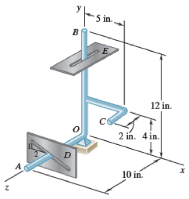
Fig. P15.201
(a)
The angular acceleration of the guide arm.
Answer to Problem 15.202P
The angular acceleration of the guide arm is
Explanation of Solution
Given information:
The velocity
Calculation:
Sketch the Free Body Diagram of the robotic guide arm as shown in Figure 1.
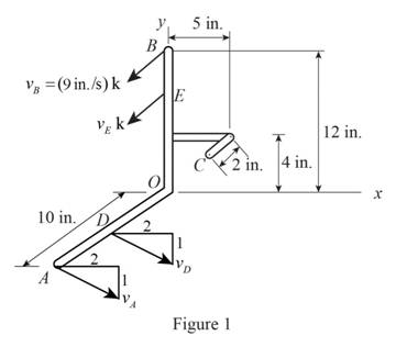
Refer to Figure 1.
The velocity at D along the x axis is
The velocity at A along the x axis is
Calculate the position vector
The position of A.
The position of B.
The position of C.
Consider the angular velocity
Consider the velocity at A
Calculate the angular velocity of each plane using the relation of
Substitute
Resolving i, j and k components.
For i component.
For k component.
Calculate the angular velocity of each plane using the relation of
Substitute
Substitute
Resolving i, j and k components.
For i component.
For j component.
For k component.
Calculate the velocity at A
Substitute
Calculate the angular velocity along y direction
Substitute
Calculate the angular velocity
Substitute
Calculate the velocity of point A
Substitute
Calculate the velocity of point C
Substitute
Consider the angular acceleration
Consider the acceleration at A
Consider the acceleration at B
Calculate the angular acceleration at B of each plane using the relation of
Substitute
Resolving i, j and k components.
For i component.
For j component.
For k component.
Calculate the angular acceleration at A of each plane using the relation of
Substitute
Substitute 0 for
Resolving i, j and k components.
For i component.
For j component.
For k component.
Refer to Figure 1.
The acceleration at A along the x axis
Substitute
Calculate the angular acceleration along y axis
Substitute
Calculate the angular acceleration
Substitute
Therefore, the angular acceleration of the guide arm is
(b)
Find the acceleration of point C.
Answer to Problem 15.202P
The acceleration of point C is
Explanation of Solution
Given information:
The velocity at B is
Calculation:
Refer to part (a).
The angular velocity of the guide arm is
The angular acceleration of the guide arm is
The velocity at C is
Calculate the acceleration at C
Substitute
Therefore, the acceleration of point C is
Want to see more full solutions like this?
Chapter 15 Solutions
Vector Mechanics for Engineers: Statics and Dynamics
Additional Engineering Textbook Solutions
DeGarmo's Materials and Processes in Manufacturing
EBK FUNDAMENTALS OF THERMODYNAMICS, ENH
Automotive Technology: Principles, Diagnosis, and Service (5th Edition)
Applied Fluid Mechanics (7th Edition)
Vector Mechanics for Engineers: Statics, 11th Edition
Fundamentals Of Thermodynamics


- Knowing that at the instant shown the angular velocity of rod AB is 15 rad/s clockwise, write down the equation of velocity of point B relative to point A. -V_Bi=(-15k)x(-0.2j) +V_Bj=V_Ai-(15k) x (0.6i+0.25j) -V_Bi=V_A+(-15k)x(0.2j) +V_Bj=V_Ai-(omega_BDk) x (-0.6i-0.25j)arrow_forwardA juggling club is thrown vertically into the air. The center of gravity G of the 20-in. club is located 12 in. from the knob. Knowing that at the instant shown, G has a velocity of 4 ft/s upward and the club has an angular velocity of 30 rad/s counterclockwise, determine (a) the speeds of points A and B, (b) the location of the instantaneous center of rotation.arrow_forwardA painter is half way up a 10-m ladder when the bottom starts sliding out from under him. Knowing that point A has a velocity vA = 2 m/s directed to the left when 0= 60°, determine (a) the angular velocity of the ladder, (b) the velocity of the painter.arrow_forward
- Consider that at the instant shown, bar AB of the mechanical system below has a angular velocity (wAB) counterclockwise at 5 rad/s and an angular acceleration (alphaAB)counterclockwise 2 rad/s².The length of bar AB is 0.4 m and the length of bar BC is 1 m. For the instant shown, and using a "Analysis of Relative Motion", determine: (a) the speed of point B (b) angular velocity of connecting bar BC (c) the speed of point C (d) the acceleration of point B (d) the acceleration of point Carrow_forwardThe earth makes one complete revolution on its axis in 23 h 56 min.Knowing that the mean radius of the earth is 3960 mi, determine the linear velocity and acceleration of a point on the surface of the earth (a) at the equator, (b) at Philadelphia, latitude 40° north, (c) at the North Pole.arrow_forwardA chain is looped around two gears of radius 40 mm that can rotate freely with respect to the 320-mm arm AB. The chain moves about arm AB in a clockwise direction at the constant rate of 80 mm/s relative to the arm. Knowing that in the position shown arm AB rotates clockwise about A at the constant rate ω = 0.75 rad/s, determine the acceleration of each of the chain links indicated Links 1 and 2.arrow_forward
- A circular plate of 120-mm radius is supported by two bearings A and B as shown. The plate rotates about the rod joining A and B with a constant angular velocity of 26 rad/s. Knowing that, at the instant considered, the velocity of point C is directed to the right, determine the velocity and acceleration of point E.arrow_forwardA circular plate of 120 mm radius is supported by two bearings A and B as shown. The plate rotates about the rod joining A and B with a constant angular velocity of 26 rad/s. Knowing that, at the instant considered, the velocity of Point C is directed to the right, determine the velocity and acceleration of Point E.arrow_forwardProblem 1: In a four bar mechanism, the dimensions of the links are as given below: AB = 50 mm, BC = 66 mm CD = 56 mm and AD = 100 mm At a given instant when |DAB 60o the angular velocity of link AB is 10.5 r/s in CCW direction. Determine, i) Velocity of point C ii) Velocity of point E on link BC when BE = 40 mm iii) The angular velocity of link BC and CD iv) The velocity of an offset point F on link BC, if BF = 45 mm, CF = 30 mm and BCF is read clockwise. v) The velocity of an offset point G on link CD, if CG = 24 mm, DG = 44 mm and DCG is read clockwise. vi) The velocity of rubbing of pins A, B, C and D. The ratio of the pins are 30 mm, 40 mm, 25 mm and 35 mm respectively.arrow_forward
- A 3-in.-radius drum is rigidly attached to a 5-in.-radius drum as shown. One of the drums rolls without sliding on the surface shown, and a cord is wound around the other drum. Knowing that at the instant shown. point A has a velocity of 5.75 in./s and an acceleration of 19 in./s2, both directed to the right, determine the accelerations of points A, B, and C of the drums. a) The accelerations of point B is _ upward? b) The accelerations of point A is _ and _? (magnitude and direction) c) The accelerations of point C is _ and _? (magnitude and direction)arrow_forwardIn a four bar mechanism, the dimensions of the links are as given below:AB = 50 mm, BC = 66 mmCD = 56 mm and AD = 100 mmAt a given instant when | DAB=60°the angular velocity of link AB is 10.5rad/sec in CCW direction.Determine,i) Velocity of point Cii) Velocity of point E on link BC when BE = 40 mmiii) The angular velocity of link BC and CDiv) The velocity of an offset point F on link BC, if BF = 45 mm,CF = 30 mm and BCF is read clockwise.v) The velocity of an offset point G on link CD, if CG = 24mm, DG = 44 mm and DCG is read clockwise.vi) The velocity of rubbing of pins A, B, C and D. The ratios ofthe pins are 30 mm, 40 mm, 25 mm and 35 mmrespectively.arrow_forward
 Elements Of ElectromagneticsMechanical EngineeringISBN:9780190698614Author:Sadiku, Matthew N. O.Publisher:Oxford University Press
 Mechanics of Materials (10th Edition)Mechanical EngineeringISBN:9780134319650Author:Russell C. HibbelerPublisher:PEARSON
 Thermodynamics: An Engineering ApproachMechanical EngineeringISBN:9781259822674Author:Yunus A. Cengel Dr., Michael A. BolesPublisher:McGraw-Hill Education
 Control Systems EngineeringMechanical EngineeringISBN:9781118170519Author:Norman S. NisePublisher:WILEY
 Mechanics of Materials (MindTap Course List)Mechanical EngineeringISBN:9781337093347Author:Barry J. Goodno, James M. GerePublisher:Cengage Learning
 Engineering Mechanics: StaticsMechanical EngineeringISBN:9781118807330Author:James L. Meriam, L. G. Kraige, J. N. BoltonPublisher:WILEY