
APPLIED STATICS & STRENGTH OF MATERIALS
null Edition
ISBN: 9781323905210
Author: Limbrunner
Publisher: PEARSON C
expand_more
expand_more
format_list_bulleted
Videos
Textbook Question
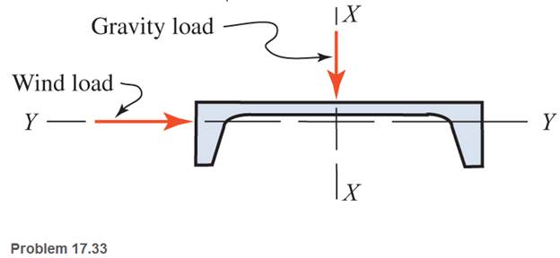
Chapter 17, Problem 17.33SP
A horizontal flexural member (a girt) in the wall of a prefabricated metal building is composed of a
Expert Solution & Answer
Want to see the full answer?
Check out a sample textbook solution
Chapter 17 Solutions
APPLIED STATICS & STRENGTH OF MATERIALS
Ch. 17 - Prob. 17.1PCh. 17 - A horizontal 30-ft simple span beam is supported...Ch. 17 - A 1-in.-by-4-in, steel bar is subjected to the...Ch. 17 - A W410100 structural steel wide-flange section is...Ch. 17 - A W1272 structural steel wide-flange section is...Ch. 17 - A solid steel shaft 3 in. in diameter and 4 ft...Ch. 17 - A short compression member is subjected to a...Ch. 17 - With reference to Problem 17.7, calculate the...Ch. 17 - A section of a 51-mm-diameter standard-weight...Ch. 17 - For the pipe of Problem 17.9, compute the maximum...
Ch. 17 - A concrete pedestal is in the shape of a cube and...Ch. 17 - 17.12 For the pedestal of Problem 17.11, assume...Ch. 17 - 17.13 Rework Problem 17.11, but assume that the...Ch. 17 - A 12-in-square concrete pedestal is subjected to a...Ch. 17 - 17.15 A short compression member is subjected to a...Ch. 17 - A rectangular concrete footing, 4 ft by 8 ft in...Ch. 17 - The bending and shear stresses developed at a...Ch. 17 - Stresses developed at a point in a machine part...Ch. 17 - Calculate the principal stresses at points A and B...Ch. 17 - 17.20 Rework Problem 17.19 using P = 8000 lb and...Ch. 17 - 17.21 A 1-in.-square steel bar is subjected to an...Ch. 17 - 17.22 A bar having a cross-sectional area of 6...Ch. 17 - Rework Problem 17.22, changing the load to a...Ch. 17 - Solve Problem l7.17 using Mohr’s circle.Ch. 17 - For the elements shown in Problem 17.18, use...Ch. 17 - Solve Problem 17.19 using Mohr’s circle.Ch. 17 - In Problem 17.19, change the load to 8000 lb and...Ch. 17 - For the following computer problems, any...Ch. 17 - For the following computer problems, any...Ch. 17 - For the following computer problems, any...Ch. 17 - For the following computer problems, any...Ch. 17 - A 4-in.-by-8-in. (S4S) Douglas fir timber beam is...Ch. 17 - A horizontal flexural member (a girt) in the wall...Ch. 17 - A simply supported W1850 structural steel...Ch. 17 - A steel link in a machine is designed to avoid...Ch. 17 - 17.36 An 8-in-square (S4S) vertical timber post is...Ch. 17 - A short 3-in.-square steel bar with a...Ch. 17 - A timber member 150 mm by 250 mm (S4S) is loaded...Ch. 17 - A concrete wall 8 ft high and 3 ft thick is...Ch. 17 - 17.40 A short compression member is subjected to a...Ch. 17 - 17.41 Calculate the maximum eccentric load that...Ch. 17 - A short compression member is subjected to two...Ch. 17 - 17.43 Calculate the force P that may be applied to...Ch. 17 - 17.44 A load of 1000 lb is supported on a...Ch. 17 - 17.45 A short compression member is subjected to...Ch. 17 - 17.46 A structural steel wide-flange section is...Ch. 17 - 17.47 A cast-iron frame for a piece of industrial...Ch. 17 - 17.48 The assembly shown is used in a machine. It...Ch. 17 - 17.49 A 50-mm-diameter solid steel shaft is...Ch. 17 - An element of a machine member is subjected to the...Ch. 17 - 17.51 A short-span cantilever built-up beam has...Ch. 17 - Solve Problem 17.50 using Mohr’s circle.Ch. 17 - 17.53 A cantilever beam is subjected to an...Ch. 17 - A 6-in.-diameter solid shaft is subjected to a...Ch. 17 - Rework parts (b) and (c) of Example 17.7 using...
Knowledge Booster


Learn more about
Need a deep-dive on the concept behind this application? Look no further. Learn more about this topic, mechanical-engineering and related others by exploring similar questions and additional content below.Similar questions
- A flying but tress transmit s a load P = 25 kN, acting at an angle of 60º to the horizontal, to the top of a vertical buttress AB (see figure). The vertical buttress has height h = 5.0 m and rectangular cross section of thickness t = 1.5 m and width b = 1.0 m (perpendicular to the plane of the figure). The stone used in the construction weighs y = 26 kN/m3. What is the required weight W of the pedestal and statue above the vertical buttress (that is, above section A) to avoid any tensile stresses in the vertical buttress?arrow_forwardDuring construction of a highway bridge, the main girders are cantilevered outward from one pier toward the next (see figure). Each girder has a cantilever length of 48 m and an I-shaped cross section with dimensions shown in the figure. The load on each girder (during construction) is assumed to be 9,5 kN/m, which includes the weight of the girder. Determine the maximum bending stress in a girder due to this load.arrow_forwardA propped cantilever beam, fixed at the left-hand end A and simply supported at the right-hand end B, is subjected to a temperature differentia] with temperature T1on its upper surface and T2on its lower surface (see figure).arrow_forward
- A bridge girder A B on a simple span of length L = 14 m supports a distributed load of maximum intensity q at m id-span and minimum intensity q/2 at supports A and B that includes the weight of the girder (sec figure). The girder is constructed of three plates welded to form the cross section shown. Determine the maximum permissible load q based upon (a) an a I lowable bending stress tra]Um = 110 M Pa and (b) an allowable shear stress r ,. = 50 M Pa.arrow_forwardA frame ABCD is constructed of steel wide-flange members (W8 x 21; E = 30 x ID6 psi) and subjected to triangularly distributed loads of maximum intensity q0acting along the vertical members (see figure). The distance between supports is L = 20 ft and the height of the frame is h = 4 ft. The members are rigidly connected at B and C. Calculate the intensity of load q0 required to produce a maximum bending moment of 80 kip-in. in the horizontal member BC. If the load q0 is reduced to one-half of the value calculated in part (a), what is the maximum bending moment in member BC? What is the ratio of this moment to the moment of 80 kip-in. in part (a)?arrow_forwardA square wood platform is 8 ft × 8 ft in area and rests on masonry walls (see figure). The deck of the platform is constructed of 2-in. nominal thickness tongue-and-groove planks (actual thickness 1.5 in.; sec Appendix CL) supported on two S-ft long beams. The beams have 4 in. × (i in. nominal dimensions (actual dimensions 3.5 in. × 5.5 in.). The planks arc designed to support a uniformly distributed load n ( lb/ft" i acting over the entire top surface of the platform. I be allowable bending stress for the planks is 2400 psi and the allowable shear stress is 100 psi. W ben analyzing the planks, disregard their weights and assume that their reactions are uniformly distributed over the top surfaces of the supporting beams. (a) Determine the allowable platform load Mr. (lb/ft2) based upon the bending stress in the planks. (b) Determine the allowable platform load if-. (lb/ft-) based upon the shear stress in the planks. (c) Which of the preceding values becomes the allowable load alolow on the platform? Hints: Use care in constructing the loading diagram for the planks, noting especially that the reactions are distributed loads instead of concentrated loads. Also, note that the maximum shear forces occur at the inside faces of the supporting beams.arrow_forward
- An S6 × 12.5 steel cantilever beam AB is supported by a steel tic rod at B as shown. The tie rod is just taut when a roller support is added at Cat a distance s to the left of £, then the distributed load q is applied to beam segment AC, Assume E = 30 × 106 psi and neglect the self-weight of the beam and tie rod. Sec Table F-2(a) in Appendix F for the properties of the S-shape beam. (a) What value of uniform load q will, if exceeded, result in buckling of the tie rod if L1, =6 ft, s = 2 ft, H = 3 ft, and d = 0.25 in.? (b) What minimum beam moment of inertia ibis required to prevent buckling of the tie rod if q = 200 lb/ft, L1, = 6 ft, H = 3 ft, d = 0.25 in., and s = 2 ft? (c) For what distance s will the tic rod be just on the verge of buckling if q = 200 lb/ft, L1= 6 ft, M = 3 ft, and d = 0.25 in.?arrow_forwardA long re Lai nine: wall is braced by wood shores set at an angle of 30° and supported by concrete thrust blocks, as shown in the first part of the figure. The shores are evenly spaced at 3 m apart. For analysis purposes, the wall and shores are idealized as shown in the second part of the figure. Note that the base of the wall and both ends of the shores are assumed to be pinned. The pressure of the soil against the wall is assumed to be triangularly distributed, and the resultant force acting on a 3-meter length of the walls is F = 190 kN. If each shore has a 150 mm X 150 mm square cross section, what is the compressive stressarrow_forwardThe cross section of a narrow-gage railway bridge is shown in part a of the figure. The bridge is constructed with longitudinal steel grinders that support the wood cross ties. The bridge is constructed with longitudinal steel girders that support the wood cross ties. The girders are restrained against lateral buckling by diagonal bracing, as indicated by the dashed lines. The spacing of the girders is S1= 50 in. and the spacing of the rails is s2= 30 in. The load transmitted by each rail to a single tie is P = 1500 1b. The cross section of a tie, shown in part b of the figure, has a width b =5.0 in. and depth d. Determine the minimum value of d based upon an allowable bending stress of 1125 psi in the wood tie. (Disregard the weight of the tie itself.)arrow_forward
- A tie-down on the deck of a sailboat consists of a bent bar boiled at both ends, as shown in the figure. The diameter dBof the bar is 1/4 in., the diameter D Wof the washers is 7/8 in., and the thickness is of the fiberglass deck is 3/8 in. If the allowable shear stress in the fiberglass is 300 psi, and the allowable bearing pressure between the washer and the fiberglass is 550 psi, what is the allowable load P allowon the tie-down?arrow_forwardTwo W 310 × 74 Steel wide-flange beams are bolted together to form a built-up beam as shown in the figure. What is the maximum permissible bolt spacing s if the shear force V = 80 kN and the allowable load in shear on each bolt is F = 13.5 kN. Note: Obtain the dimensions and properties of the W shapes from Table F-l(b).arrow_forwardA retaining wall (Fig. a) is constructed using steel W-shape columns and concrete panel infill (Fig, b). Each column is subjected to lateral soil pressure with peak intensity q0(Figs, b and c). The tensile and compressive strength of the beam is 600 MPa. Select the most economical W 360 section from Table F-l(b) based on safety factor of 3.0.arrow_forward
arrow_back_ios
SEE MORE QUESTIONS
arrow_forward_ios
Recommended textbooks for you
 Mechanics of Materials (MindTap Course List)Mechanical EngineeringISBN:9781337093347Author:Barry J. Goodno, James M. GerePublisher:Cengage Learning
Mechanics of Materials (MindTap Course List)
Mechanical Engineering
ISBN:9781337093347
Author:Barry J. Goodno, James M. Gere
Publisher:Cengage Learning
Mechanics of Materials Lecture: Beam Design; Author: UWMC Engineering;https://www.youtube.com/watch?v=-wVs5pvQPm4;License: Standard Youtube License