
APPLIED STATICS & STRENGTH OF MATERIALS
null Edition
ISBN: 9781323905210
Author: Limbrunner
Publisher: PEARSON C
expand_more
expand_more
format_list_bulleted
Videos
Textbook Question
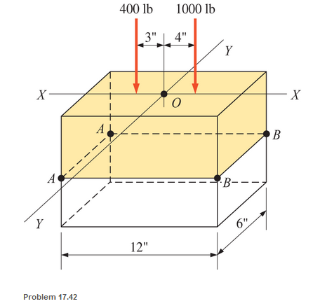
Chapter 17, Problem 17.42SP
A short compression member is subjected to two compressive loads, as shown. The member is 6 in. by 12 in. in cross section. Calculate the combined stress at outer edges AA and BB.
Expert Solution & Answer
Want to see the full answer?
Check out a sample textbook solution
Students have asked these similar questions
the right -angled frame in a uniformly distributed loading equivalent to 200 N for each horizontal projected meter of the frame; tha is, the total load is 1000 N. compute the maximum flexural stress at section a-a if the cross section is a 50 mm square.
A bar having a cross-section areas of 700mm2 is subjected to axial loads at the positions indicated,find the value of stress in the segment QR
A thin walled spherical shell is subjected to an internal pressure. If the radius of the shell is increased by 1% and the thickness is reduced by 1%, with the internal pressure remaining the same, the percentage change in the circumferential (hoop) stress is.....
Chapter 17 Solutions
APPLIED STATICS & STRENGTH OF MATERIALS
Ch. 17 - Prob. 17.1PCh. 17 - A horizontal 30-ft simple span beam is supported...Ch. 17 - A 1-in.-by-4-in, steel bar is subjected to the...Ch. 17 - A W410100 structural steel wide-flange section is...Ch. 17 - A W1272 structural steel wide-flange section is...Ch. 17 - A solid steel shaft 3 in. in diameter and 4 ft...Ch. 17 - A short compression member is subjected to a...Ch. 17 - With reference to Problem 17.7, calculate the...Ch. 17 - A section of a 51-mm-diameter standard-weight...Ch. 17 - For the pipe of Problem 17.9, compute the maximum...
Ch. 17 - A concrete pedestal is in the shape of a cube and...Ch. 17 - 17.12 For the pedestal of Problem 17.11, assume...Ch. 17 - 17.13 Rework Problem 17.11, but assume that the...Ch. 17 - A 12-in-square concrete pedestal is subjected to a...Ch. 17 - 17.15 A short compression member is subjected to a...Ch. 17 - A rectangular concrete footing, 4 ft by 8 ft in...Ch. 17 - The bending and shear stresses developed at a...Ch. 17 - Stresses developed at a point in a machine part...Ch. 17 - Calculate the principal stresses at points A and B...Ch. 17 - 17.20 Rework Problem 17.19 using P = 8000 lb and...Ch. 17 - 17.21 A 1-in.-square steel bar is subjected to an...Ch. 17 - 17.22 A bar having a cross-sectional area of 6...Ch. 17 - Rework Problem 17.22, changing the load to a...Ch. 17 - Solve Problem l7.17 using Mohr’s circle.Ch. 17 - For the elements shown in Problem 17.18, use...Ch. 17 - Solve Problem 17.19 using Mohr’s circle.Ch. 17 - In Problem 17.19, change the load to 8000 lb and...Ch. 17 - For the following computer problems, any...Ch. 17 - For the following computer problems, any...Ch. 17 - For the following computer problems, any...Ch. 17 - For the following computer problems, any...Ch. 17 - A 4-in.-by-8-in. (S4S) Douglas fir timber beam is...Ch. 17 - A horizontal flexural member (a girt) in the wall...Ch. 17 - A simply supported W1850 structural steel...Ch. 17 - A steel link in a machine is designed to avoid...Ch. 17 - 17.36 An 8-in-square (S4S) vertical timber post is...Ch. 17 - A short 3-in.-square steel bar with a...Ch. 17 - A timber member 150 mm by 250 mm (S4S) is loaded...Ch. 17 - A concrete wall 8 ft high and 3 ft thick is...Ch. 17 - 17.40 A short compression member is subjected to a...Ch. 17 - 17.41 Calculate the maximum eccentric load that...Ch. 17 - A short compression member is subjected to two...Ch. 17 - 17.43 Calculate the force P that may be applied to...Ch. 17 - 17.44 A load of 1000 lb is supported on a...Ch. 17 - 17.45 A short compression member is subjected to...Ch. 17 - 17.46 A structural steel wide-flange section is...Ch. 17 - 17.47 A cast-iron frame for a piece of industrial...Ch. 17 - 17.48 The assembly shown is used in a machine. It...Ch. 17 - 17.49 A 50-mm-diameter solid steel shaft is...Ch. 17 - An element of a machine member is subjected to the...Ch. 17 - 17.51 A short-span cantilever built-up beam has...Ch. 17 - Solve Problem 17.50 using Mohr’s circle.Ch. 17 - 17.53 A cantilever beam is subjected to an...Ch. 17 - A 6-in.-diameter solid shaft is subjected to a...Ch. 17 - Rework parts (b) and (c) of Example 17.7 using...
Knowledge Booster


Learn more about
Need a deep-dive on the concept behind this application? Look no further. Learn more about this topic, mechanical-engineering and related others by exploring similar questions and additional content below.Similar questions
- A 15 in diameter rod is subjected to an axial tensile load of 45 kips. Compute. a. The normal stress developed on an inclined plane at an angle of 60° with the cross section of the rod. b. The maximum normal stress developed in the rod.arrow_forwardA circular tube AB is fixed at one end and free at the other end. The tubeis subjected to axialforce at joint B. If the outer diameter of the tube is 3 in, and thethickness is 3/4 in., calculate the maximum normal stress in the tubearrow_forwardA compressive load of 219 kN is resisted by a rectangular strut which has one side measuring 83 mm. If the stress in the strut is 164 909 kPa, what is the length of the other side of the strut?arrow_forward
- A thin cylindrical pressure vessel with closed-ends is subjected to internal pressure. The ratio of circumferential (hoop) stress to the longitudinal stress is?arrow_forwardCalculate the principal stresses at point A for the loading case.arrow_forwardWrite down the stress types acting on each bar in the supported beam system above.arrow_forward
- a) Calculate the maximum and average stresses un sections A and B, take t= 0.45inarrow_forwardThe cross-sectional area of each member of the truss shown in the figure. Calculate the stress in member EFarrow_forwardThe turnbuckles in the diagram shown are tightened until the compression block DB exerts a force of 12,365lb on the beam at B. Member DB is a hollow shaft with an inner diameter of 1.0 inch and outer diameter of 2 inches. Rods AD and CD each have cross-sectional areas of 1.1 square inches. Pin C has a diameter of 0.78 inch. Determine the following: a.The axial stress, in psi, in BD. b.The axial stress, in psi, in CD.c.The shearing stress, in psi, in pin C.arrow_forward
- A tube from aluminium with an outside diameter of 50 (mm) and a wall thickness of 5 (mm) is used as a compression member. If the axial normal stress in the member must be limited to 90 MPa, what is the maximum force (in kN) that the member can support.arrow_forwardcircular tube AB is fixed at one end andfree at the other end. The tube is subjected to axialforce at joint B. If the outer diameter of the tube is 75 mm and the thickness is 19 mm, calculate the max-imum normal stress in the tube.arrow_forwardVertical load is applied to point B of a 10 mm radius cylindrical bar as shown in the figure. Calculate the shear stress occurring in the point.arrow_forward
arrow_back_ios
SEE MORE QUESTIONS
arrow_forward_ios
Recommended textbooks for you
 Elements Of ElectromagneticsMechanical EngineeringISBN:9780190698614Author:Sadiku, Matthew N. O.Publisher:Oxford University Press
 Mechanics of Materials (10th Edition)Mechanical EngineeringISBN:9780134319650Author:Russell C. HibbelerPublisher:PEARSON
 Thermodynamics: An Engineering ApproachMechanical EngineeringISBN:9781259822674Author:Yunus A. Cengel Dr., Michael A. BolesPublisher:McGraw-Hill Education
 Control Systems EngineeringMechanical EngineeringISBN:9781118170519Author:Norman S. NisePublisher:WILEY
 Mechanics of Materials (MindTap Course List)Mechanical EngineeringISBN:9781337093347Author:Barry J. Goodno, James M. GerePublisher:Cengage Learning
 Engineering Mechanics: StaticsMechanical EngineeringISBN:9781118807330Author:James L. Meriam, L. G. Kraige, J. N. BoltonPublisher:WILEY
Elements Of Electromagnetics
Mechanical Engineering
ISBN:9780190698614
Author:Sadiku, Matthew N. O.
Publisher:Oxford University Press
Mechanics of Materials (10th Edition)
Mechanical Engineering
ISBN:9780134319650
Author:Russell C. Hibbeler
Publisher:PEARSON
Thermodynamics: An Engineering Approach
Mechanical Engineering
ISBN:9781259822674
Author:Yunus A. Cengel Dr., Michael A. Boles
Publisher:McGraw-Hill Education
Control Systems Engineering
Mechanical Engineering
ISBN:9781118170519
Author:Norman S. Nise
Publisher:WILEY
Mechanics of Materials (MindTap Course List)
Mechanical Engineering
ISBN:9781337093347
Author:Barry J. Goodno, James M. Gere
Publisher:Cengage Learning
Engineering Mechanics: Statics
Mechanical Engineering
ISBN:9781118807330
Author:James L. Meriam, L. G. Kraige, J. N. Bolton
Publisher:WILEY
Mechanics of Materials Lecture: Beam Design; Author: UWMC Engineering;https://www.youtube.com/watch?v=-wVs5pvQPm4;License: Standard Youtube License