
APPLIED STATICS & STRENGTH OF MATERIALS
null Edition
ISBN: 9781323905210
Author: Limbrunner
Publisher: PEARSON C
expand_more
expand_more
format_list_bulleted
Concept explainers
Videos
Textbook Question
Chapter 17, Problem 17.11P
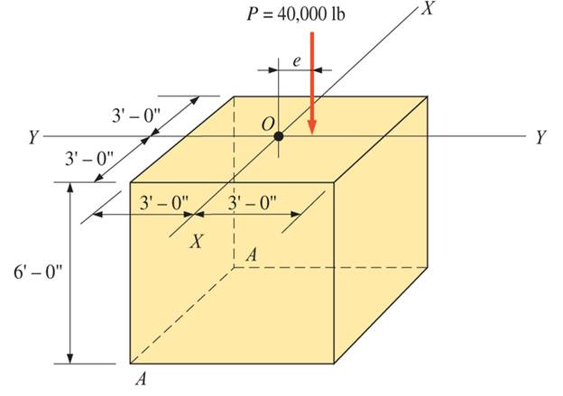
A concrete pedestal is in the shape of a cube and is 6 ft on each side. The pedestal supports a superimposed load of 40,000 lb located on the Y-Y axis, as shown. Calculate the maximum eccentricity e for zero tension at the base of the pedestal. Include the weight of the pedestal using a concrete unit weight of 150 pcf.

Expert Solution & Answer
Want to see the full answer?
Check out a sample textbook solution
Students have asked these similar questions
The triangular block below is subjected to the Loads P=1200 lb and 400 lb. If AB=8 in, and BC is 6in., resolve each load into components normal and tangential to AC.
Given bar having cross-sectional area of 700mm^2 is subjected to axial loads at the positions indicated.
1. A non-uniform bar weighs 400N and is 4m long. When it is supported by a fulcrum at its midpoint, a load of 80N must be supplied at the smaller end to hold the bar in a horizontal position. Where is the center of gravity?
With complete solution
Chapter 17 Solutions
APPLIED STATICS & STRENGTH OF MATERIALS
Ch. 17 - Prob. 17.1PCh. 17 - A horizontal 30-ft simple span beam is supported...Ch. 17 - A 1-in.-by-4-in, steel bar is subjected to the...Ch. 17 - A W410100 structural steel wide-flange section is...Ch. 17 - A W1272 structural steel wide-flange section is...Ch. 17 - A solid steel shaft 3 in. in diameter and 4 ft...Ch. 17 - A short compression member is subjected to a...Ch. 17 - With reference to Problem 17.7, calculate the...Ch. 17 - A section of a 51-mm-diameter standard-weight...Ch. 17 - For the pipe of Problem 17.9, compute the maximum...
Ch. 17 - A concrete pedestal is in the shape of a cube and...Ch. 17 - 17.12 For the pedestal of Problem 17.11, assume...Ch. 17 - 17.13 Rework Problem 17.11, but assume that the...Ch. 17 - A 12-in-square concrete pedestal is subjected to a...Ch. 17 - 17.15 A short compression member is subjected to a...Ch. 17 - A rectangular concrete footing, 4 ft by 8 ft in...Ch. 17 - The bending and shear stresses developed at a...Ch. 17 - Stresses developed at a point in a machine part...Ch. 17 - Calculate the principal stresses at points A and B...Ch. 17 - 17.20 Rework Problem 17.19 using P = 8000 lb and...Ch. 17 - 17.21 A 1-in.-square steel bar is subjected to an...Ch. 17 - 17.22 A bar having a cross-sectional area of 6...Ch. 17 - Rework Problem 17.22, changing the load to a...Ch. 17 - Solve Problem l7.17 using Mohr’s circle.Ch. 17 - For the elements shown in Problem 17.18, use...Ch. 17 - Solve Problem 17.19 using Mohr’s circle.Ch. 17 - In Problem 17.19, change the load to 8000 lb and...Ch. 17 - For the following computer problems, any...Ch. 17 - For the following computer problems, any...Ch. 17 - For the following computer problems, any...Ch. 17 - For the following computer problems, any...Ch. 17 - A 4-in.-by-8-in. (S4S) Douglas fir timber beam is...Ch. 17 - A horizontal flexural member (a girt) in the wall...Ch. 17 - A simply supported W1850 structural steel...Ch. 17 - A steel link in a machine is designed to avoid...Ch. 17 - 17.36 An 8-in-square (S4S) vertical timber post is...Ch. 17 - A short 3-in.-square steel bar with a...Ch. 17 - A timber member 150 mm by 250 mm (S4S) is loaded...Ch. 17 - A concrete wall 8 ft high and 3 ft thick is...Ch. 17 - 17.40 A short compression member is subjected to a...Ch. 17 - 17.41 Calculate the maximum eccentric load that...Ch. 17 - A short compression member is subjected to two...Ch. 17 - 17.43 Calculate the force P that may be applied to...Ch. 17 - 17.44 A load of 1000 lb is supported on a...Ch. 17 - 17.45 A short compression member is subjected to...Ch. 17 - 17.46 A structural steel wide-flange section is...Ch. 17 - 17.47 A cast-iron frame for a piece of industrial...Ch. 17 - 17.48 The assembly shown is used in a machine. It...Ch. 17 - 17.49 A 50-mm-diameter solid steel shaft is...Ch. 17 - An element of a machine member is subjected to the...Ch. 17 - 17.51 A short-span cantilever built-up beam has...Ch. 17 - Solve Problem 17.50 using Mohr’s circle.Ch. 17 - 17.53 A cantilever beam is subjected to an...Ch. 17 - A 6-in.-diameter solid shaft is subjected to a...Ch. 17 - Rework parts (b) and (c) of Example 17.7 using...
Knowledge Booster


Learn more about
Need a deep-dive on the concept behind this application? Look no further. Learn more about this topic, mechanical-engineering and related others by exploring similar questions and additional content below.Similar questions
- A ladder with a uniform cross-section has a length of 4.80-foot long. It weighs W Ib. It is arranged such that one end is on the ground and the other against a vertical wall. The angle of triction at all contact surtaces is 20 degrees. What is the value of the coefficient of triction? What is f, in terms of variable Na? What is the normal force at A in terms of variable W? Answer in three decimal placesarrow_forwardFind the load on each bar of the cage given below. Its dimensions are base 2a and height 3a. EB passes through the midpoint of the lattice. Angle of force F1= 700 with horizontal (choose an angle between 15o and 75o)arrow_forwardThe total axial load acting at the centroid at on the leftmost rib would be 2F2 and the total axial load acting at the centroid at section C would be 2F3 A) Assume that the axial member is in equilibrium and the applied forces are an unknown load F1, F2 = 11 kN , F3 = 9 kN , and F4 = 6 kN . Calculate the internal resultant normal force at section B. B) Calculate the internal resultant normal force at section D. C)Suppose the axial member has a circular cross section with a diameter of dB = 16 cm at section B and a diameter of dD = 8 cm at section D. What is the average normal stress in the section with the maximum magnitude stress?arrow_forward
- The timber column in Fig. is made from two boards nailed together sothat the cross section has the dimensions shown. If the column is fixed at itsbase and free at its top, use to determine the eccentric load P that can be supported.arrow_forwardCompute the internal diameter of the 10 m length hollow cast iron column. If the externaldiameter is two times the internal diameter and the safe compressive load on a hollowcast iron column with one end rigidly fixed and other end hinged is 60 kN. Use Euler’sformula with a factor of safety of 3 and E = 90 kN/mm2arrow_forwardA mechanism used in printing machinery consists of a helical spring which is having a wire diameter of 5mm and an outside diameter of 54mm. The spring has 16 active coils. If the permissible shear stress of the spring material is 335 N/mm2 and the Modulus of rigidity is 82 kN/mm2. a) Calculate the axial load in N and the deflection of the spring in mm, neglecting the effect of curvature. b) Calculate the value of axial load in N considering the effect of curvature.arrow_forward
- The structure shown below consists of an arch AB and an elastic column BC. (Note: Joints where members meet can be treated as pin). Calculate the weight, W, that causes the column to buckle. Determine the support reactions corresponding to the weight from the previous question. Given:a = 3.430 marrow_forwardSHOW COMPLETE SOLUTION AND ILLUSTRATION FINAL ANSWER IN 3 DECIMAL PLACES Problem 2: A circular rod tapers in diameter from 50 mm from one end to 20 mmon theother end for a length of 12 m. it is attached to the ceiling with its bigger end and a load P= 85 kN is suspended at its lower end. The rod has E = 200 GPa. Compute the deformation of the rod due to this load. Neglect the weight of the bar.arrow_forwardCalculate x if point B contacted with the square support? (Erod CD=200GPa; AB is a rigid bar without deformation)arrow_forward
- Find the maximum load P that can be supported by the tripod If the force in any legs is limited to 2000N. Assume that the legs are two-force bodies.arrow_forwardThe rigid bars AB and CD, as shown in the figure, are supported by pins at A and C and the two aluminum and steel rods. Determine the maximum force P that can be applied if its motion vertical is limited to 5mm. Ignore the weights of all members. The figure is in the attached image.arrow_forwardDraw the free-body diagram for the following problem. The cantilever footing shown.arrow_forward
arrow_back_ios
SEE MORE QUESTIONS
arrow_forward_ios
Recommended textbooks for you
 Elements Of ElectromagneticsMechanical EngineeringISBN:9780190698614Author:Sadiku, Matthew N. O.Publisher:Oxford University Press
 Mechanics of Materials (10th Edition)Mechanical EngineeringISBN:9780134319650Author:Russell C. HibbelerPublisher:PEARSON
 Thermodynamics: An Engineering ApproachMechanical EngineeringISBN:9781259822674Author:Yunus A. Cengel Dr., Michael A. BolesPublisher:McGraw-Hill Education
 Control Systems EngineeringMechanical EngineeringISBN:9781118170519Author:Norman S. NisePublisher:WILEY
 Mechanics of Materials (MindTap Course List)Mechanical EngineeringISBN:9781337093347Author:Barry J. Goodno, James M. GerePublisher:Cengage Learning
 Engineering Mechanics: StaticsMechanical EngineeringISBN:9781118807330Author:James L. Meriam, L. G. Kraige, J. N. BoltonPublisher:WILEY
Elements Of Electromagnetics
Mechanical Engineering
ISBN:9780190698614
Author:Sadiku, Matthew N. O.
Publisher:Oxford University Press
Mechanics of Materials (10th Edition)
Mechanical Engineering
ISBN:9780134319650
Author:Russell C. Hibbeler
Publisher:PEARSON
Thermodynamics: An Engineering Approach
Mechanical Engineering
ISBN:9781259822674
Author:Yunus A. Cengel Dr., Michael A. Boles
Publisher:McGraw-Hill Education
Control Systems Engineering
Mechanical Engineering
ISBN:9781118170519
Author:Norman S. Nise
Publisher:WILEY
Mechanics of Materials (MindTap Course List)
Mechanical Engineering
ISBN:9781337093347
Author:Barry J. Goodno, James M. Gere
Publisher:Cengage Learning
Engineering Mechanics: Statics
Mechanical Engineering
ISBN:9781118807330
Author:James L. Meriam, L. G. Kraige, J. N. Bolton
Publisher:WILEY
EVERYTHING on Axial Loading Normal Stress in 10 MINUTES - Mechanics of Materials; Author: Less Boring Lectures;https://www.youtube.com/watch?v=jQ-fNqZWrNg;License: Standard YouTube License, CC-BY