Videos
A rod subject to an axial load (Fig. P24.41a) will be de-formed, as shown in the stress-strain curve in Fig. P24.41b. The area under the curve from zero stress out to the point of rupture is called the modulus of toughness of the material. It providesa measure of the energy per unit volume required to cause the material to rupture. As such, it is representative of the material's ability to withstand an impact load. Use numerical
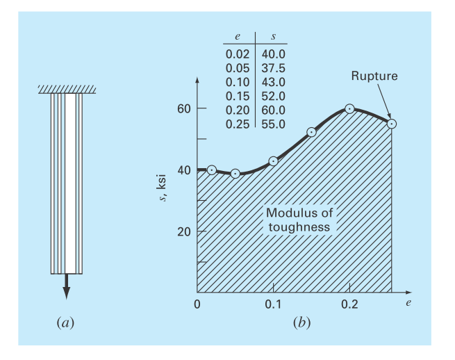
FIGURE P24.41: (a) A rod under axial loading and (b) the resulting stress-strain curve where stress is in kipsper square inch
Want to see the full answer?
Check out a sample textbook solution
Chapter 24 Solutions
EBK NUMERICAL METHODS FOR ENGINEERS


- The materials laboratory that you direct received the following data on the tensile strength in MPa of 15 samples of Aluminum Nitride. The data obtained for each sample are: Sample Endurance (Mpa) SAMPLE (STRENGTH) MPa 1 190 2 233 3 268 4 160 5 257 6 300 7 310 8 262 9 185 10 205 11 275 12 245 13 220 14 290 15 228 You are asked to calculate the Weibull modulus, m, considering that the probability of failure is n/16, where n is the number of specimens that failed at a given stress. You can use Excel to speed up the calculations.arrow_forward100 80 60 40 20 0.002 0.004 0.006 0.008 0.01 0.012 Strain, in/in. FIGURE P1.17 1.18 Use Problem 1.17 to graphically determine the following: a. Modulus of resilience b. Toughness Hint: The toughness (u) can be determined by calculating the area under the stress-strain curve u = de where & is the strain at fracture. The preceding integral can be approxi- mated numerically by using a trapezoidal integration technique: u, = Eu, = o, + o e, - 6) %3D c. If the specimen is loaded to 40 ksi only and the lateral strain was found to be -0.00057 in./in., what is Poisson's ratio of this metal? d. If the specimen is loaded to 70 ksi only and then unloaded, what is the permanent strain? Stress, ksiarrow_forwardA long steel rod is placed horizontally between two supports, one at each end. The rod bends a little in the center. Which property of this rod can be used to estimate how much the rod should bend at the center? 1. Its Shear Modulus 2. Its Young's Modulus 3. All of these Moduli can be used to compute how much it bends. 4. Its Bulk Modulus.arrow_forward
- Q6.1 There are always imperfections in a crystalline structure. Perfect order never exists throughout crystalline materials on an atomic scale. All crystalline structures contain large numbers of defects and imperfections. Name and explain two types of defects in crystalline solid. Q6.2 Heat treatment may be used to improve the mechanical properties of some aluminium alloys. Heat treatment for aluminium alloys is done via a process called precipitation hardening also known as age hardening. Explain the steps of age hardening and name one example of aluminium alloy which can be strengthened by age hardening.arrow_forwardA physics lab consists of a large ball attached to a wire. Students hold on to one end of the wire, then whirl the ball around in circles and count the number of rotations per second. One group finds these numbers: ball mass= 320 gram, wire length= 1.3m, number of rotations/sec=2.5. The wire is made of steel with a diameter of 1mm and a Young's modulus of 20x10^10 N/m^2.How much does the wire stretch due to the tension on it? Should the students correct their data for the wire stretching?arrow_forwardQ7. A 1.85 m long solid bar (Lo) with a 22 mm diameter is placed under tension by a load (F) of 125 kN. This solid bar is made of a homogeneous material with a Young's Modulus E = 150 GPa. Calculate the extension of the bar (AL). Give your answer in millimetres (mm) to two decimal places. F Answer: Lo L AL Farrow_forward
- At 90 degrees of knee flexion, the mechanical stress at the tibiofemoral joint is 821.43 N/cm^2. If the compressive force is 1150 N, what is the magnitude of joint contact area (in cm^2)?arrow_forward(a) Write equations for the internal forces at J (axial (F), shear (V), and bending (M)) in terms of only P and a. (b) Graph your equations as functions of P, using a = 45°, from 0 < P < 1000 N. Use your graph to answer the following conceptual questions: 1. Which quantity (F, V, or M) is most affected by changes in P? 2. Based on your diagrams and graphical results, for positive values of P... I. Is point J under tension or compression? II. If the structure fails (snaps) at a point just to the right of J, which direction does your diagram indicate point J will travel (up or down)? III. Which direction do your results indicate member BC will tend to bend, concave up or down? 3. For different values of a, what will happen to these lines? Choose all that apply: a. They will shift up/down b. They will shift left/right c. They will rotate (change slope) d. Nothing (c) Graph your equations as functions of a, using P = 100 N, from 0 < a < 2π. Use your graph to identify what value of a…arrow_forwardupper leg muscle 9 cm in radius). 2) Don't ever try the acorn diet, its nuts. In the tree diagrammed here, a force of 800 N is exerted at the tip of the limb (equivalent to the weight of "800 apples). The limb is circular in cross-section and 2 m long with a tip radius of 3 cm a base radius of 10 cm. The radius increases linearly from the tip to the base. Plot the tensile stress at the top of the limb along its length. Where along the length would you expect the limb to break? M. X. Lo Yarrow_forward
- For the problem shown in Fig Q1(a), elastic contact stress between a cylindrical punch and a fixed base plate when a displacement (Uy) is applied can be simulated using FE method. With appropriate sketches for geometry, boundary conditions, and areas for mesh refinement of the model, outline how convergence study can be carried out for the problem. (Note: no detailed drawing of mesh is required.). Mention and justify element types to be used for the model. Describe clearly the parameter to be used for the convergence study. Uy Fig Q1(a): Contact problem between a cylindrical punch and a platearrow_forward2. For the mild steel part drawing below (Fig. Q5.2) (Mair, 1993), previ- ously considered in the problems for Chapters 3 and 4, identify suitable production equipment and tooling to manufacture it. Use the solutions from the previous chapters as the basis for your answer. Only consider equipment/tooling described in this chapter. Ø30 R6 1×45° |0,8% 0.8 40 10,00 9.80 80士0.01 MATERIAL: Mild Steel Ø30mm Figure Q5.2 OIW Ø30 Ø10arrow_forward1. A metal wire 20 mm in diameter and 3 m long hangs vertically with a 5 kg object suspended from it. If the wire stretches 2 mm under the tension, what is the value of Young's modulus for the metal?arrow_forward
 Elements Of ElectromagneticsMechanical EngineeringISBN:9780190698614Author:Sadiku, Matthew N. O.Publisher:Oxford University Press
 Mechanics of Materials (10th Edition)Mechanical EngineeringISBN:9780134319650Author:Russell C. HibbelerPublisher:PEARSON
 Thermodynamics: An Engineering ApproachMechanical EngineeringISBN:9781259822674Author:Yunus A. Cengel Dr., Michael A. BolesPublisher:McGraw-Hill Education
 Control Systems EngineeringMechanical EngineeringISBN:9781118170519Author:Norman S. NisePublisher:WILEY
 Mechanics of Materials (MindTap Course List)Mechanical EngineeringISBN:9781337093347Author:Barry J. Goodno, James M. GerePublisher:Cengage Learning
 Engineering Mechanics: StaticsMechanical EngineeringISBN:9781118807330Author:James L. Meriam, L. G. Kraige, J. N. BoltonPublisher:WILEY