
Tutorials in Introductory Physics
1st Edition
ISBN: 9780130970695
Author: Peter S. Shaffer, Lillian C. McDermott
Publisher: Addison Wesley
expand_more
expand_more
format_list_bulleted
Concept explainers
Videos
Textbook Question
Chapter 24.3, Problem 2bTH
A very small, very bright bulb is placed for from a semi−cylindrical mirror. The bulb is located on the axis of the mirror. Some light rays from the distant bulb are shown in the diagram below.
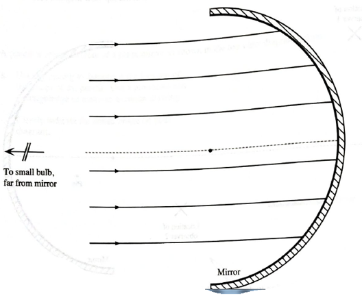
- Is there a well−defined focal point for the (entire) mirror?
| If so: | Identify and label the focal point on the diagram. Explain how you used your ray diagram to determine your answer. |
| If not: | Identify and label the approximate portion of the mirror for which a focal point is well defined. Identify and label the focal point for this portion of the mirror. Explain how you used your ray diagram to determine your answers. |
Expert Solution & Answer
Want to see the full answer?
Check out a sample textbook solution
Students have asked these similar questions
Analyse the following observation table showing variation of image distance with object distance in case of a convex lens and answer the question that follow without doing any calculations1) What is the focal length of the convex lens? Give reason in support of your answer2) Write the serial number of that observation which is not correct. How did you arrive at this conclusion.3) Take an appropriate scale to draw ray diagram for the observation at S. No. 4 and find the approximate value of the magnification.Class - 10thChapter - Light, reflection and refraction.
A ray of light travels through air until it strikes the interface between the air and another medium. The incident ray makes an angle of ?1 = 33.0° with the normal, as shown in the figure below. Upon passage into the second medium, the ray is refracted, emerging from the interface at an angle ?2 with respect to the normal.
(a)Suppose that the second medium is ice. What is the angle of refraction, ?2 (in degrees)? (Enter your answer to at least one decimal place.)
(b)Suppose that the second medium is crown glass. What is the angle of refraction, ?2,in this case (in degrees)? (Enter your answer to at least one decimal place.)
(c)Finally, suppose that the second medium is ethyl alcohol. What is the angle of refraction, ?2, in this case (in degrees)? (Enter your answer to at least one decimal place.)
A concave lens refracts parallel rays in such a way that they are bent away from the axis of the lens. For this reason, a concave lens is referred to as a diverging lens.
Part A: Consider the following diagrams, where F represents the focal point of a concave lens. In these diagrams, the image formed by the lens is obtained using the ray tracing technique. Which diagrams are accurate?(Figure 1)
*Type A if you think that only diagram A is correct, type AB if you think that only diagrams A and B are correct, and so on.
Part B: If the focal length of the concave lens is -7.50 cm , at what distance d_o from the lens should an object be placed so that its image is formed 3.70 cm from the lens?
Chapter 24 Solutions
Tutorials in Introductory Physics
Ch. 24.1 - On the diagram, sketch what you would see on the...Ch. 24.1 - The small bulb is replaced by three longfilament...Ch. 24.1 - The three longfilament bulbs are replaced by a...Ch. 24.1 - Predict the size and shape of the shadow that will...Ch. 24.1 - Is it possible to place the bulb in another...Ch. 24.1 - Prob. 2cTHCh. 24.1 - Prob. 2dTHCh. 24.1 - Prob. 3aTHCh. 24.1 - A student is looking at the building shown at...Ch. 24.1 - Prob. 4aTH
Ch. 24.1 - Suppose that this student were walking through the...Ch. 24.2 - The top view diagrams at right were drawn by a...Ch. 24.2 - Draw a ray diagram to determine the location of...Ch. 24.2 - Describe how you could use a ray diagram to...Ch. 24.2 - A pencil is placed in front of a plane mirror as...Ch. 24.2 - Prob. 3bTHCh. 24.3 - Prob. 1aTHCh. 24.3 - A pin is placed in front of a semicylindrical...Ch. 24.3 - Prob. 1cTHCh. 24.3 - Prob. 2aTHCh. 24.3 - A very small, very bright bulb is placed for from...Ch. 24.4 - The following are top view diagrams of solid...Ch. 24.4 - The following are top view diagrams of solid...Ch. 24.4 - The following are top view diagrams of solid...Ch. 24.4 - The following are top view diagrams of solid...Ch. 24.4 - Prob. 2THCh. 24.4 - Prob. 3aTHCh. 24.4 - Prob. 3bTHCh. 24.4 - Is the image(s) of the nail real or virtual?...Ch. 24.5 - Suppose that the bulb is placed as shown. Using...Ch. 24.5 - Prob. 1bTHCh. 24.5 - Prob. 1cTHCh. 24.5 - Prob. 1dTHCh. 24.5 - Prob. 2aTHCh. 24.5 - Treat the image produced by lens 1 as an object...Ch. 24.5 - Repeat parts a andb for the case in which lens 2...Ch. 24.6 - Reproduced below is a side view diagram of the...Ch. 24.6 - In section III of the tutorial Magnification, you...Ch. 24.6 - Two thin convex lenses and an object are arranged...Ch. 24.6 - Prob. 3bTHCh. 24.6 - Two thin convex lenses and an object are arranged...Ch. 24.6 - Prob. 3dTHCh. 24.6 - Two thin convex lenses and an object are arranged...
Additional Science Textbook Solutions
Find more solutions based on key concepts
Explain all answers clearly, with complete sentences and proper essay structure if needed. An asterisk (*) desi...
Cosmic Perspective Fundamentals
The minimum possible thickness of the gasoline layer.
College Physics: A Strategic Approach (3rd Edition)
21. Two -diameter aluminum electrodes are spaced apart.
The electrodes are connected to a battery.
...
Physics for Scientists and Engineers: A Strategic Approach with Modern Physics (4th Edition)
An electron is inside a solenoid, 28 cm from the axis. It experiences a 1.3-fN electric force. At what rate is ...
Essential University Physics (3rd Edition)
A 20.0m -tall hollow aluminium flagpole is equivalent in strength to a solid cylinder 4.00cm in diameter. A str...
University Physics Volume 1
Q25.22 A fuse is a device designed to break a circuit, usually by melting when the current exceeds a certain va...
University Physics (14th Edition)
Knowledge Booster


Learn more about
Need a deep-dive on the concept behind this application? Look no further. Learn more about this topic, physics and related others by exploring similar questions and additional content below.Similar questions
- Construct ray diagrams to determine the location, orientation, size, and type of images formed by a curved mirror. Using the protractor and the ruler, copy each of the diagrams (A – F) below on a separate sheet of paper. As much as possible, use the four principal rays to locate the image formed in a curved mirror.arrow_forwardMIRROR/LENS EQUATION 1. Suppose that the height of the object is 3.00 cm at 20.0 cm from the concave mirror. What are the height and the distance of the image from the mirror if the focal length is 10.0 cm? 2. What is the local length of a convex mirror that produces an image that appears 20.0 cm behind the mirror when the object is 35.0 cm from the mirror? 3. Complete the given table. Show your solution. ( The table is provided in the picture.) Please answer question nos. 1, 2 and 3. Thank you!!arrow_forwardThe ray diagrams shown trace the path that light takes in order to locate the image formed by a concave mirror. Points C and f indicate the mirror's center center of curvature and focal point. Which ray diagrams are drawn incorrectly.arrow_forward
- The prism in the figure below is made of glass with an index of refraction of 1.63 for blue light and 1.61 for red light. Find ?R, the angle of deviation for red light, and ?B, the angle of deviation for blue light, if white light is incident on the prism at an angle of 30.0°. (Enter your answers in degrees.) see image attached (a) ?R, the angle of deviation for red light (b) ?B, the angle of deviation for blue lightarrow_forwardAn image seen through a convex mirror cut from a sphere of radius 20cm is exactly half size of the object. Where must the object and image be located? Support your work with a ray diagram. Hint: Remember that virtual distances are negative when using the mirror equation. Follow grading rubric. Explain answer.arrow_forwardThe prism in the diagram is being used as a mirror. (a) Construct a ray diagram to indicate how the light entering the prism travels. Show how it reflects off the back face and also where the reflected ray leaves the prism. (b) Is point A, B, C, D, or E most likely to intercept an outgoing ray? (c) The incoming ray hits the back left face of the prism at what angle? (in terms of the normal to the back face) (d) A reflected ray leaves the back left face of the prism at what angle? (e) What is the index of refraction of the prism if the ray experiences total internal reflection when it hits the back face of the prism?arrow_forward
- A beam of light travels vertically downward and strikes a horizontal mirror, reflecting directly back vertically upward, as indicated by the black dashed line in the diagram at left. The mirror is now rotated, so that it is 10° away from horizontal, as is the red mirror in the diagram . The incident solid black ray is the same in both cases. a) At what angle from the vertical will the reflected beam (the red dashed arrow) now be seen? b) If the mirror is further rotated until it is 20° from the horizontal, what will be the new angle between the reflected beam and the vertical?arrow_forwardDraw a ray diagram for each of the following, and then draw the image formed. Please provide complete labels in the diagrams, as well as the size, orientation, type, and position of the image. Thank you so much! You may only opt to answer number 2 if answering all is not allowed:) 1. Object location at 2F’ 2. Object location at F’ 3. Object location beyond 2F’arrow_forwardLens and mirror practice! Draw ray diagrams for each of the following scenarios, and check your results using the lens/mirror equation. (a) Concave mirror, object at 2f. (b) Convex mirror, object at 2f. (c) Converging lens, object at f/2. (d) Diverging lens, object at f/2. (e) Two closely spaced converging lenses with the same focal length f, object at 2f. (Hint: Draw two separate ray diagrams; treat the image of the first lens as the object of the second—but be careful if the object ends up being virtual!) (f) Briefly discuss: can a convex mirror or diverging lens ever produce a real image? If not, why not; if yes, how?arrow_forward
- Draw a ray diagram for the concave mirror with the presence of a point-like light source place at the focal point you already marked. Using diagrams belowarrow_forwarddescribe how a ray diagram can be used to show the location of an image formed by a concave mirror. Describe the rays that can be used, where they travel before and after striking the mirror, and where the images form.arrow_forwardFour ray diagrams are shown below. f1, f2 are the focal points for the lenses respectively as shown from left to right. when both focal points occur at the same point their position is designated as "f1/f2". Identify the TWO ray diagrams that show the correct position for the FINAL image for the two-lens systems shown below.arrow_forward
arrow_back_ios
SEE MORE QUESTIONS
arrow_forward_ios
Recommended textbooks for you
 Glencoe Physics: Principles and Problems, Student...PhysicsISBN:9780078807213Author:Paul W. ZitzewitzPublisher:Glencoe/McGraw-Hill
Glencoe Physics: Principles and Problems, Student...
Physics
ISBN:9780078807213
Author:Paul W. Zitzewitz
Publisher:Glencoe/McGraw-Hill
AP Physics 2 - Geometric Optics: Mirrors and Lenses - Intro Lesson; Author: N. German;https://www.youtube.com/watch?v=unT297HdZC0;License: Standard YouTube License, CC-BY