
University Physics with Modern Physics (14th Edition)
14th Edition
ISBN: 9780321973610
Author: Hugh D. Young, Roger A. Freedman
Publisher: PEARSON
expand_more
expand_more
format_list_bulleted
Videos
Textbook Question
Chapter 26, Problem 26.65P
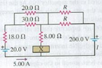
In the circuit shown in Fig. P26.65, the current in the 20.0-V battery is 5.00 A in the direction shown and the voltage across the 8.00 Ω resistor is 16.0 V. with the lower end of the resistor at higher potential. Find (a) the emf (including its polarity) of the battery X; (b) the current I through the 200.0-V battery (including its direction); (c) the resistance R.
Figure P26.65
Expert Solution & Answer

Trending nowThis is a popular solution!

Learn your wayIncludes step-by-step video

schedule06:38
Students have asked these similar questions
A car battery with a 12 V emf and an internal resistance of 0.040 is being charged with a current of 50 A. What are (a) the potential difference V across the terminals, (b) the rate Pr of energy dissipation inside the battery, and (c) the rate Pemf of energy conversion to chemical form? When the battery is used to supply 50 A to the starter motor, what are (d) V and (e) Pr?
When charging a capacitor in series with a resistor, using a 10 V emf source, what would you expect the voltage of the capacitor to be at an initial time of t = τ ?
a. 3.68 V
b. 0.368 V
c. 6.32 V
d. 10 V
e. 0.632 V
Where a 9 V battery is connected to a network of resistors with R1 = 72 Ω, R2 = 132 Ω, R3 = 18 Ω, and R4 = 36 Ω. What is the current produced by the battery? (in A)a. 0.943 Ab. 0.0349 Ac. 0.125 Ad. 0.188 A
Chapter 26 Solutions
University Physics with Modern Physics (14th Edition)
Ch. 26.1 - Suppose all three of the resistors shown in Fig....Ch. 26.2 - Subtract Eq. (1) from Eq. (2) in Example 26.6. To...Ch. 26.3 - You want to measure the current through and the...Ch. 26.4 - The energy stored in a capacitor is equal to...Ch. 26.5 - To prevent the circuit breaker in Example 26.14...Ch. 26 - In which 120-V light bulb does the filament have...Ch. 26 - Two 120-V light bulbs, one 25-W and one 200-W,...Ch. 26 - You connect a number of identical light bulbs to a...Ch. 26 - In the circuit shown in Fig. Q26.4, three...Ch. 26 - If two resistors R1 and R2 (R2 R1) are connected...
Ch. 26 - If two resistors R1 and R2 (R2 R1) are connected...Ch. 26 - A battery with no internal resistance is connected...Ch. 26 - A resistor consists of three identical metal...Ch. 26 - A light bulb is connected in the circuit shown in...Ch. 26 - A real battery, having nonnegligible internal...Ch. 26 - If the battery in Discussion Question Q26.10 is...Ch. 26 - Consider the circuit shown in Fig. Q26.12. What...Ch. 26 - Is it possible to connect resistors together in a...Ch. 26 - The battery in the circuit shown in Fig. Q26.14...Ch. 26 - In a two-cell flashlight, the batteries are...Ch. 26 - Identical light bulbs A, B, and C are connected as...Ch. 26 - The emf of a flashlight battery is roughly...Ch. 26 - Will the capacitors in the circuits shown in Fig....Ch. 26 - Verify that the time constant RC has units of...Ch. 26 - For very large resistances it is easy to construct...Ch. 26 - When a capacitor, battery, and resistor are...Ch. 26 - A uniform wire of resistance R is cut into three...Ch. 26 - A machine part has a resistor X protruding from an...Ch. 26 - A resistor with R1 = 25.0 is connected to a...Ch. 26 - A 42- resistor and a 20- resistor are connected in...Ch. 26 - A triangular array of resistors is shown in Fig....Ch. 26 - For the circuit shown in Fig. E26.6 both meters...Ch. 26 - For the circuit shown in Fig. E26.7 find the...Ch. 26 - Three resistors having resistances of 1.60 , 2.40...Ch. 26 - Now the three resistors of Exercise 26.8 are...Ch. 26 - Power Rating of a Resistor. The power rating of a...Ch. 26 - In Fig. E26.11, R1, = 3.00 , R2 = 6.00 , and R3=...Ch. 26 - In Fig. E26.11 the battery has emf 35.0 V and...Ch. 26 - Compute the equivalent resistance of the network...Ch. 26 - Compute the equivalent resistance of the network...Ch. 26 - In the circuit of Fig. E26.15, each resistor...Ch. 26 - Consider the circuit shown in Fig. E26.16. The...Ch. 26 - In the circuit shown in Fig. E26.17, the voltage...Ch. 26 - In the circuit shown in Fig. E26.18, = 36.0 V,...Ch. 26 - CP In the circuit in Fig. E26.19, a 20.0- resistor...Ch. 26 - In the circuit shown in Fig. E26.20, the rate at...Ch. 26 - Light Bulbs in Series and in Parallel. Two light...Ch. 26 - Light Bulbs in Series. A 60-W, 120-V light bulb...Ch. 26 - In the circuit shown in Fig. E26.23, ammeter A1...Ch. 26 - The batteries shown in the circuit in Fig. E26.24...Ch. 26 - In the circuit shown in Fig. E26.25 find (a) the...Ch. 26 - Find the emfs 1 and 2 in the circuit of Fig....Ch. 26 - In the circuit shown in Fig. E26.27, find (a) the...Ch. 26 - In the circuit shown in Fig. E26.28, find (a) the...Ch. 26 - The 10.00-V battery in Fig. E26.28 is removed from...Ch. 26 - The 5.00-V battery in Fig. E26.28 is removed from...Ch. 26 - In the circuit shown in Fig. E26.31 the batteries...Ch. 26 - In the circuit shown in Fig. E26.32 both batteries...Ch. 26 - In the circuit shown in Fig. E26.33 all meters are...Ch. 26 - In the circuit shown in Fig. E26.34, the 6.0-...Ch. 26 - The resistance of a galvanometer coil is 25.0 ,...Ch. 26 - The resistance of the coil of a pivoted coil...Ch. 26 - A circuit consists of a series combination of...Ch. 26 - A galvanometer having a resistance of 25.0 has a...Ch. 26 - A capacitor is charged to a potential of 12.0 V...Ch. 26 - You connect a battery, resistor, and capacitor as...Ch. 26 - A 4.60-F capacitor that is initially uncharged is...Ch. 26 - You connect a battery, resistor, and capacitor as...Ch. 26 - CP In the circuit shown in Fig. E26.43 both...Ch. 26 - A 12.4-F capacitor is connected through a 0.895-M...Ch. 26 - An emf source with = 120 V, a resistor with R =...Ch. 26 - A resistor and a capacitor are connected in series...Ch. 26 - CP In the circuit shown in Fig. E26.47 each...Ch. 26 - A 1.50-F capacitor is charging through a 12.0-...Ch. 26 - In the circuit in Fig. E26.49 the capacitors are...Ch. 26 - A 12.0-F capacitor is charged to a potential of...Ch. 26 - In the circuit shown in Fig. E26.51, C = 5.90 F, ...Ch. 26 - Prob. 26.52ECh. 26 - A 1500-W electric beater is plugged into the...Ch. 26 - In Fig. P26.54, the battery has negligible...Ch. 26 - The two identical light bulbs in Example 26.2...Ch. 26 - Each of the three resistors in Fig. P26.56 has a...Ch. 26 - (a) Find the potential of point a with respect to...Ch. 26 - CP For the circuit shown in Fig. P26.58 a 20.0-...Ch. 26 - Calculate the three currents I1, I2, and I3...Ch. 26 - What must the emf in Fig. P26.60 be in order for...Ch. 26 - Find the current through each of the three...Ch. 26 - (a) Find the current through the battery and each...Ch. 26 - Consider the circuit shown in Fig. P26.63. (a)...Ch. 26 - In the circuit shown in Fig. P26.64, = 24.0 V,...Ch. 26 - In the circuit shown in Fig. P26.65, the current...Ch. 26 - In the circuit shown in Fig. P26.66 all the...Ch. 26 - Figure P26.67 employs a convention often used in...Ch. 26 - Three identical resistors are connected in series....Ch. 26 - A resistor R1 consumes electrical power P1 when...Ch. 26 - The capacitor in Fig. F26.70 is initially...Ch. 26 - A 2.00-F capacitor that is initially uncharged is...Ch. 26 - A 6.00-F capacitor that is initially uncharged is...Ch. 26 - Point a in Fig. P26.73 is maintained at a constant...Ch. 26 - The Wheatstone Bridge. The circuit shown in Fig....Ch. 26 - (See Problem 26.67.) (a) What is the potential of...Ch. 26 - A 2.36-F capacitor that is initially uncharged is...Ch. 26 - A 224- resistor and a 589- resistor are connected...Ch. 26 - A resistor with R = 850 is connected to the...Ch. 26 - A capacitor that is initially uncharged is...Ch. 26 - DATA You set up the circuit shown in Fig. 26.22a,...Ch. 26 - DATA You set up the circuit shown in Fig. 26.20....Ch. 26 - DATA The electronics supply company where you work...Ch. 26 - An Infinite Network. As shown in Fig. P26.83, a...Ch. 26 - Suppose a resistor R lies along each edge of a...Ch. 26 - BIO Attenuator Chains and Axons. The infinite...Ch. 26 - Assume that a typical open ion channel spanning an...Ch. 26 - In a simple model of an axon conducting a nerve...Ch. 26 - Cell membranes across a wide variety of organisms...
Additional Science Textbook Solutions
Find more solutions based on key concepts
Check Your Understanding A long solenoid of cross-section area 5.0 cm2is wound with 25 turns of wire pet centim...
University Physics Volume 2
The pV-diagram of the Carnot cycle.
Sears And Zemansky's University Physics With Modern Physics
Explain all answers clearly, with complete sentences and proper essay structure if needed. An asterisk (*) desi...
The Cosmic Perspective Fundamentals (2nd Edition)
Formula One race cars have 66-cm-diameter tires. If a Formula One averages a speed of 300 km/h during a race, w...
University Physics Volume 1
(a) Show that .
[Hint: Use integration by parts.]
(b) Let be the step function: . (1.95)
Show that .
Introduction to Electrodynamics
3. What is free-fall, and why does it make you weightless? Briefly describe why astronauts are weightless in th...
The Cosmic Perspective (8th Edition)
Knowledge Booster


Learn more about
Need a deep-dive on the concept behind this application? Look no further. Learn more about this topic, physics and related others by exploring similar questions and additional content below.Similar questions
- In Figure P29.81, N real batteries, each with an emf and internal resistance r, are connected in a closed ring. A resistor R can be connected across any two points of this ring, causing there to be n real batteries in one branch and N n resistors in the other branch. Find an expression for the current through the resistor R in this case.arrow_forwardA battery is used to charge a capacitor through a resistor as shown in Figure P27.44. Show that half the energy supplied by the battery appears as internal energy in the resistor and half is stored in the capacitor. Figure P27.44arrow_forwardThe values of the components in a simple series RC circuit containing a switch (Fig. P21.53) are C = 1.00 F, R = 2.00 106 , and = 10.0 V. At the instant 10.0 s after the switch is closed, calculate (a) the charge on the capacitor, (b) the current in the resistor, (c) the rate at which energy is being stored in the capacitor, and (d) the rate at which energy is being delivered by the battery.arrow_forward
- A 12.0-V emf automobile battery has a terminal voltage of 16.0 V when being charged by a current of 10.0 A. (a) What is the battery’s internal resistance? (b) What power is dissipated inside the battery? (c) At what rate (in °C/min ) will its temperature increase if its mass is 20.0 kg and it has a specific heat of 0.300 kcal/kg • °C, assuming no heat escapes?arrow_forwardTwo 1.50-V batterieswith their positive terminals in the same directionare inserted in series into a flashlight. One battery has an internal resistance of 0.255 , and the other has an internal resistance of 0.153 . When the switch is closed, the bulb carries a current of 600 mA. (a) What is the bulbs resistance? (b) What fraction of the chemical energy transformed appears as internal energy in the batteries?arrow_forwardElectric current I enters a node with three resistors connected in parallel (Fig. CQ18.5). Which one of the following is correct? (a) I1 = I and I2 = I3 = 0. (b) I2 I1 and I2 I3. (c) V1 V2 V3 (d) I1 I2 I3 0. Figure CQ18.5arrow_forward
- Electric current I enters a node with three resistors connected in parallel (Fig. CQ18.5). Which one of the following is correct? (a) I1 = I and I2 = I3 = 0. (b) I2 I1 and I2 I3. (c) V1 V2 V3 (d) I1 I2 I3 0. Figure CQ18.5arrow_forwardFour resistors are connected to a battery as shown in Figure P21.40. The current in the battery is I, the battery emf is , and the resistor values are R1 = R, R2 = 2R, R3 = 4R, and R4 = 3R. (a) Rank the resistors according to the potential difference across them, from largest to smallest. Note any cases of equal potential differences. (b) Determine the potential difference across each resistor in terms of . (c) Rank the resistors according to the current in them, from largest to smallest. Note any cases of equal currents. (d) Determine the current in each resistor in terms of I. (e) If R3 is increased, what happens to the current in each of the resistors? (f) In the limit that R3 , what are the new values of the current in each resistor in terms of I, the original current in the battery? Figure P21.40arrow_forwardWhere a 9 V battery is connected to a network of resistors with R1 = 72 Ω, R2 = 132 Ω, R3 = 18 Ω, and R4 = 36 Ω. What is the current through R2? (in V)a. 0.0625 Ab. 0.188 Ac. 0.0938 Ad. 0.0682 Aarrow_forward
- In the figure the ideal batteries have emfs 1 = 13.1 V and 2 = 4.17 V, and the resistances are each 4.02 Ω. What are the (a) magnitude and (b) direction of i1 and the (c) magnitude and (d) direction of i2? (e) Does battery 1 supply or absorb energy, and (f) what is its energy transfer rate? (g) Does battery 2 supply or absorb energy, and (h) what is its energy transfer rate?arrow_forwardA circuit consisting of 5 resistors is shown in the graph. Their resistances are R1 = 16 Ω, R2 = 55 Ω, R3 = 97 Ω, R4 = 63 Ω, and R5 = 23 Ω, and the emf of the battery is ε = 5.5 V. Suppose the internal resistance of the battery is zero. Express the current I through R1 in terms of the emf ε and the equivalent resistance R.arrow_forward
arrow_back_ios
arrow_forward_ios
Recommended textbooks for you
 College PhysicsPhysicsISBN:9781305952300Author:Raymond A. Serway, Chris VuillePublisher:Cengage Learning
 College PhysicsPhysicsISBN:9781285737027Author:Raymond A. Serway, Chris VuillePublisher:Cengage Learning
 Physics for Scientists and Engineers: Foundations...PhysicsISBN:9781133939146Author:Katz, Debora M.Publisher:Cengage Learning
 Principles of Physics: A Calculus-Based TextPhysicsISBN:9781133104261Author:Raymond A. Serway, John W. JewettPublisher:Cengage Learning
 Physics for Scientists and EngineersPhysicsISBN:9781337553278Author:Raymond A. Serway, John W. JewettPublisher:Cengage Learning
 Physics for Scientists and Engineers with Modern ...PhysicsISBN:9781337553292Author:Raymond A. Serway, John W. JewettPublisher:Cengage Learning
College Physics
Physics
ISBN:9781305952300
Author:Raymond A. Serway, Chris Vuille
Publisher:Cengage Learning
College Physics
Physics
ISBN:9781285737027
Author:Raymond A. Serway, Chris Vuille
Publisher:Cengage Learning
Physics for Scientists and Engineers: Foundations...
Physics
ISBN:9781133939146
Author:Katz, Debora M.
Publisher:Cengage Learning
Principles of Physics: A Calculus-Based Text
Physics
ISBN:9781133104261
Author:Raymond A. Serway, John W. Jewett
Publisher:Cengage Learning
Physics for Scientists and Engineers
Physics
ISBN:9781337553278
Author:Raymond A. Serway, John W. Jewett
Publisher:Cengage Learning
Physics for Scientists and Engineers with Modern ...
Physics
ISBN:9781337553292
Author:Raymond A. Serway, John W. Jewett
Publisher:Cengage Learning
DC Series circuits explained - The basics working principle; Author: The Engineering Mindset;https://www.youtube.com/watch?v=VV6tZ3Aqfuc;License: Standard YouTube License, CC-BY