
University Physics with Modern Physics (14th Edition)
14th Edition
ISBN: 9780321973610
Author: Hugh D. Young, Roger A. Freedman
Publisher: PEARSON
expand_more
expand_more
format_list_bulleted
Videos
Textbook Question
Chapter 26, Problem 26.19E
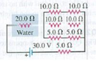
CP In the circuit in Fig. E26.19, a 20.0-Ω resistor is inside 100 g of pure water that is surrounded by insulating styrofoam. If the water is initially at 10.0°C, how long will it take for its temperature to rise to 58.0°C?
Figure E26.19
Expert Solution & Answer

Learn your wayIncludes step-by-step video

schedule06:55
Students have asked these similar questions
A 12.0 V emf automobile battery has a terminal voltage of 14.0 V when being charged by a current of 10.8 A. a) What is the battery's internal resistance (in Ω)? b) What power (in W) is dissipated inside the battery? c) At what rate (in °C/min) will its temperature increase if its mass is 20.0 kg and it has a specific heat of 0.360 kcal/(kg · °C), assuming no heat escapes?
An engineer needs a resistor with a zero overall temperature coefficient of resistance at 20.0°C. She designs a pair of circular cylinders, one of carbon and one of Nichrome as shown in Figure P17.30. The device must have an overall resistance of R1 + R2 = 10.0 Ω independent of temperature and a uniform radius of r = 1.50 mm. Ignore thermal expansion of the cylinders and assume both are always at the same temperature. (a) Can she meet the design goal with this method? (b) If so, state what you can determine about the lengths L1 and L2 of each segment. If not, explain.
A car battery with a 12 V emf and an internal resistance of 0.040 is being charged with a current of 50 A. What are (a) the potential difference V across the terminals, (b) the rate Pr of energy dissipation inside the battery, and (c) the rate Pemf of energy conversion to chemical form? When the battery is used to supply 50 A to the starter motor, what are (d) V and (e) Pr?
Chapter 26 Solutions
University Physics with Modern Physics (14th Edition)
Ch. 26.1 - Suppose all three of the resistors shown in Fig....Ch. 26.2 - Subtract Eq. (1) from Eq. (2) in Example 26.6. To...Ch. 26.3 - You want to measure the current through and the...Ch. 26.4 - The energy stored in a capacitor is equal to...Ch. 26.5 - To prevent the circuit breaker in Example 26.14...Ch. 26 - In which 120-V light bulb does the filament have...Ch. 26 - Two 120-V light bulbs, one 25-W and one 200-W,...Ch. 26 - You connect a number of identical light bulbs to a...Ch. 26 - In the circuit shown in Fig. Q26.4, three...Ch. 26 - If two resistors R1 and R2 (R2 R1) are connected...
Ch. 26 - If two resistors R1 and R2 (R2 R1) are connected...Ch. 26 - A battery with no internal resistance is connected...Ch. 26 - A resistor consists of three identical metal...Ch. 26 - A light bulb is connected in the circuit shown in...Ch. 26 - A real battery, having nonnegligible internal...Ch. 26 - If the battery in Discussion Question Q26.10 is...Ch. 26 - Consider the circuit shown in Fig. Q26.12. What...Ch. 26 - Is it possible to connect resistors together in a...Ch. 26 - The battery in the circuit shown in Fig. Q26.14...Ch. 26 - In a two-cell flashlight, the batteries are...Ch. 26 - Identical light bulbs A, B, and C are connected as...Ch. 26 - The emf of a flashlight battery is roughly...Ch. 26 - Will the capacitors in the circuits shown in Fig....Ch. 26 - Verify that the time constant RC has units of...Ch. 26 - For very large resistances it is easy to construct...Ch. 26 - When a capacitor, battery, and resistor are...Ch. 26 - A uniform wire of resistance R is cut into three...Ch. 26 - A machine part has a resistor X protruding from an...Ch. 26 - A resistor with R1 = 25.0 is connected to a...Ch. 26 - A 42- resistor and a 20- resistor are connected in...Ch. 26 - A triangular array of resistors is shown in Fig....Ch. 26 - For the circuit shown in Fig. E26.6 both meters...Ch. 26 - For the circuit shown in Fig. E26.7 find the...Ch. 26 - Three resistors having resistances of 1.60 , 2.40...Ch. 26 - Now the three resistors of Exercise 26.8 are...Ch. 26 - Power Rating of a Resistor. The power rating of a...Ch. 26 - In Fig. E26.11, R1, = 3.00 , R2 = 6.00 , and R3=...Ch. 26 - In Fig. E26.11 the battery has emf 35.0 V and...Ch. 26 - Compute the equivalent resistance of the network...Ch. 26 - Compute the equivalent resistance of the network...Ch. 26 - In the circuit of Fig. E26.15, each resistor...Ch. 26 - Consider the circuit shown in Fig. E26.16. The...Ch. 26 - In the circuit shown in Fig. E26.17, the voltage...Ch. 26 - In the circuit shown in Fig. E26.18, = 36.0 V,...Ch. 26 - CP In the circuit in Fig. E26.19, a 20.0- resistor...Ch. 26 - In the circuit shown in Fig. E26.20, the rate at...Ch. 26 - Light Bulbs in Series and in Parallel. Two light...Ch. 26 - Light Bulbs in Series. A 60-W, 120-V light bulb...Ch. 26 - In the circuit shown in Fig. E26.23, ammeter A1...Ch. 26 - The batteries shown in the circuit in Fig. E26.24...Ch. 26 - In the circuit shown in Fig. E26.25 find (a) the...Ch. 26 - Find the emfs 1 and 2 in the circuit of Fig....Ch. 26 - In the circuit shown in Fig. E26.27, find (a) the...Ch. 26 - In the circuit shown in Fig. E26.28, find (a) the...Ch. 26 - The 10.00-V battery in Fig. E26.28 is removed from...Ch. 26 - The 5.00-V battery in Fig. E26.28 is removed from...Ch. 26 - In the circuit shown in Fig. E26.31 the batteries...Ch. 26 - In the circuit shown in Fig. E26.32 both batteries...Ch. 26 - In the circuit shown in Fig. E26.33 all meters are...Ch. 26 - In the circuit shown in Fig. E26.34, the 6.0-...Ch. 26 - The resistance of a galvanometer coil is 25.0 ,...Ch. 26 - The resistance of the coil of a pivoted coil...Ch. 26 - A circuit consists of a series combination of...Ch. 26 - A galvanometer having a resistance of 25.0 has a...Ch. 26 - A capacitor is charged to a potential of 12.0 V...Ch. 26 - You connect a battery, resistor, and capacitor as...Ch. 26 - A 4.60-F capacitor that is initially uncharged is...Ch. 26 - You connect a battery, resistor, and capacitor as...Ch. 26 - CP In the circuit shown in Fig. E26.43 both...Ch. 26 - A 12.4-F capacitor is connected through a 0.895-M...Ch. 26 - An emf source with = 120 V, a resistor with R =...Ch. 26 - A resistor and a capacitor are connected in series...Ch. 26 - CP In the circuit shown in Fig. E26.47 each...Ch. 26 - A 1.50-F capacitor is charging through a 12.0-...Ch. 26 - In the circuit in Fig. E26.49 the capacitors are...Ch. 26 - A 12.0-F capacitor is charged to a potential of...Ch. 26 - In the circuit shown in Fig. E26.51, C = 5.90 F, ...Ch. 26 - Prob. 26.52ECh. 26 - A 1500-W electric beater is plugged into the...Ch. 26 - In Fig. P26.54, the battery has negligible...Ch. 26 - The two identical light bulbs in Example 26.2...Ch. 26 - Each of the three resistors in Fig. P26.56 has a...Ch. 26 - (a) Find the potential of point a with respect to...Ch. 26 - CP For the circuit shown in Fig. P26.58 a 20.0-...Ch. 26 - Calculate the three currents I1, I2, and I3...Ch. 26 - What must the emf in Fig. P26.60 be in order for...Ch. 26 - Find the current through each of the three...Ch. 26 - (a) Find the current through the battery and each...Ch. 26 - Consider the circuit shown in Fig. P26.63. (a)...Ch. 26 - In the circuit shown in Fig. P26.64, = 24.0 V,...Ch. 26 - In the circuit shown in Fig. P26.65, the current...Ch. 26 - In the circuit shown in Fig. P26.66 all the...Ch. 26 - Figure P26.67 employs a convention often used in...Ch. 26 - Three identical resistors are connected in series....Ch. 26 - A resistor R1 consumes electrical power P1 when...Ch. 26 - The capacitor in Fig. F26.70 is initially...Ch. 26 - A 2.00-F capacitor that is initially uncharged is...Ch. 26 - A 6.00-F capacitor that is initially uncharged is...Ch. 26 - Point a in Fig. P26.73 is maintained at a constant...Ch. 26 - The Wheatstone Bridge. The circuit shown in Fig....Ch. 26 - (See Problem 26.67.) (a) What is the potential of...Ch. 26 - A 2.36-F capacitor that is initially uncharged is...Ch. 26 - A 224- resistor and a 589- resistor are connected...Ch. 26 - A resistor with R = 850 is connected to the...Ch. 26 - A capacitor that is initially uncharged is...Ch. 26 - DATA You set up the circuit shown in Fig. 26.22a,...Ch. 26 - DATA You set up the circuit shown in Fig. 26.20....Ch. 26 - DATA The electronics supply company where you work...Ch. 26 - An Infinite Network. As shown in Fig. P26.83, a...Ch. 26 - Suppose a resistor R lies along each edge of a...Ch. 26 - BIO Attenuator Chains and Axons. The infinite...Ch. 26 - Assume that a typical open ion channel spanning an...Ch. 26 - In a simple model of an axon conducting a nerve...Ch. 26 - Cell membranes across a wide variety of organisms...
Additional Science Textbook Solutions
Find more solutions based on key concepts
(a) Show that .
[Hint: Use integration by parts.]
(b) Let be the step function: . (1.95)
Show that .
Introduction to Electrodynamics
Why does an observer measure waves from an approaching source as having a higher frequency than if the source w...
Conceptual Integrated Science
8. Modern wind turbines are larger than they appear, and despite their apparently lazy motion, the speed of the...
College Physics: A Strategic Approach (4th Edition)
90. How is a hydraulic pump that produces sustained water flow analogous to a battery or generator?
Conceptual Physical Science (6th Edition)
Write the SI unit for each abbreviation.
29. 27 mm
Applied Physics (11th Edition)
43. The peak current through an inductor is 12.5 mA when connected to an AC source with a peak voltage of 1.0 V...
College Physics: A Strategic Approach (3rd Edition)
Knowledge Booster


Learn more about
Need a deep-dive on the concept behind this application? Look no further. Learn more about this topic, physics and related others by exploring similar questions and additional content below.Similar questions
- If the terminals of a battery with zero internal resistance are connected across two identical resistors in series, the total power delivered by the battery is 8.00 W. If the same battery is connected across the same resistors in parallel, what is the total power delivered by the battery? (a) 16.0 W (b) 32.0 W (c) 2.00 W (d) 4.00 W (e) none of those answersarrow_forwardA battery is used to charge a capacitor through a resistor as shown in Figure P27.44. Show that half the energy supplied by the battery appears as internal energy in the resistor and half is stored in the capacitor. Figure P27.44arrow_forwardThe circuit shown in Figure P21.47 is connected for 2.00 min. (a) Determine the current in each branch of the circuit. (b) Find the energy delivered by each battery. (c) Find the energy delivered to each resistor. (d) Identify the type of energy storage transformation that occurs in the operation of the circuit. (e) Find the total amount of energy transformed into internal energy in the resistors. Figure P21.47 Problems 47 and 48.arrow_forward
- In the circuit of Figure P21.51, determine (a) the current in each resistor and (b) the potential difference across the 200- resistor. Figure P21.51arrow_forwardTwo 1.50-V batterieswith their positive terminals in the same directionare inserted in series into a flashlight. One battery has an internal resistance of 0.255 , and the other has an internal resistance of 0.153 . When the switch is closed, the bulb carries a current of 600 mA. (a) What is the bulbs resistance? (b) What fraction of the chemical energy transformed appears as internal energy in the batteries?arrow_forwardLightbulb A is marked 25.0 W 120. V, and lightbulb B is marked 100. W 120. V. These labels mean that each lightbulb has its respective power delivered to it when it is connected to a constant 120.-V source. (a) Find the resistance of each lightbulb. (b) During what time interval does 1.00 C pass into lightbulb A? (c) Is this charge different upon its exit versus its entry into the lightbulb? Explain. (d) In what time interval does 1.00 J pass into lightbulb A? (e) By what mechanisms does this energy enter and exit the lightbulb? Explain. (f) Find the cost of running lightbulb A continuously for 30.0 days, assuming the electric company sells its product at 0.110 per kWh.arrow_forward
- A potential difference of 1.00 V is maintained across a 10.0- resistor for a period of 20.0 s. What total charge passes by a point in one of the wires connected to the resistor in this time interval? (a) 200 C (b) 20.0 C (c) 2.00 C (d) 0.005 00 C (e) 0.050 0 Carrow_forwardCalculate the equivalent resistance between points P and Q of the electrical network shown in Figure P29.80.arrow_forwardThree resistors, R1 = 2.55 Ω, R2 = 4.77 Ω, and R3 = 6.55 Ω are connected by ideal metal wires, as shown in the figure. If the voltage dropping through R1 is 4.86 V, what is the power dissipated by R3 (in W)?arrow_forward
- Where a 9 V battery is connected to a network of resistors with R1 = 72 Ω, R2 = 132 Ω, R3 = 18 Ω, and R4 = 36 Ω. What is the current produced by the battery? (in A)a. 0.943 Ab. 0.0349 Ac. 0.125 Ad. 0.188 Aarrow_forwardA nichrome wire and an aluminum wire, each with the same initial resistance, have the same change in resistance when heated separately. (ρρAI=2.82 x 10⁻⁸ohm.m ; ααAI = 3.9 x 10⁻³/°C; ρρhichrome = 2.50 x 10⁻⁶ m ; ααnichrome =0.40 x 10⁻³ / °C.) The ratio of the temperature change of the nichrome wire to thetemperature change of the aluminum wire is Select one: a. 10 b. 9.75 c. 0.1 d. 1arrow_forwardWhere a 9 V battery is connected to a network of resistors with R1 = 72 Ω, R2 = 132 Ω, R3 = 18 Ω, and R4 = 36 Ω. What is the current through R2? (in V)a. 0.0625 Ab. 0.188 Ac. 0.0938 Ad. 0.0682 Aarrow_forward
arrow_back_ios
SEE MORE QUESTIONS
arrow_forward_ios
Recommended textbooks for you
 Principles of Physics: A Calculus-Based TextPhysicsISBN:9781133104261Author:Raymond A. Serway, John W. JewettPublisher:Cengage Learning
 Physics for Scientists and EngineersPhysicsISBN:9781337553278Author:Raymond A. Serway, John W. JewettPublisher:Cengage Learning
 Physics for Scientists and Engineers with Modern ...PhysicsISBN:9781337553292Author:Raymond A. Serway, John W. JewettPublisher:Cengage Learning
 Physics for Scientists and Engineers: Foundations...PhysicsISBN:9781133939146Author:Katz, Debora M.Publisher:Cengage Learning
 College PhysicsPhysicsISBN:9781305952300Author:Raymond A. Serway, Chris VuillePublisher:Cengage Learning
Principles of Physics: A Calculus-Based Text
Physics
ISBN:9781133104261
Author:Raymond A. Serway, John W. Jewett
Publisher:Cengage Learning
Physics for Scientists and Engineers
Physics
ISBN:9781337553278
Author:Raymond A. Serway, John W. Jewett
Publisher:Cengage Learning
Physics for Scientists and Engineers with Modern ...
Physics
ISBN:9781337553292
Author:Raymond A. Serway, John W. Jewett
Publisher:Cengage Learning
Physics for Scientists and Engineers: Foundations...
Physics
ISBN:9781133939146
Author:Katz, Debora M.
Publisher:Cengage Learning
College Physics
Physics
ISBN:9781305952300
Author:Raymond A. Serway, Chris Vuille
Publisher:Cengage Learning
DC Series circuits explained - The basics working principle; Author: The Engineering Mindset;https://www.youtube.com/watch?v=VV6tZ3Aqfuc;License: Standard YouTube License, CC-BY