
University Physics with Modern Physics (14th Edition)
14th Edition
ISBN: 9780321973610
Author: Hugh D. Young, Roger A. Freedman
Publisher: PEARSON
expand_more
expand_more
format_list_bulleted
Videos
Textbook Question
Chapter 26, Problem 26.62P
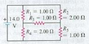
(a) Find the current through the battery and each resistor in the circuit shown in Fig. P26.62. (b) What is the equivalent resistance of the resistor network?
Figure P26.62
Expert Solution & Answer

Learn your wayIncludes step-by-step video

schedule07:33
Students have asked these similar questions
Compute the equivalent resistance of the network in Fig. E26.13, and find the current in each resistor
The batteries have emfs of E1=9.0V and E2=12.0V and the resistors have values of R1=28Ω, R2=65Ω, and R3=39Ω. Determine the magnitudes of the currents in each resistor shown in the figure. Ignore internal resistance of the batteries? Determine the directions of the currents in each resistor. Ignore internal resistance of the batteries?
In the figure below, the ideal batteries have emfs ℰ1 = 12 V, ℰ2 = 6.0 V, and the resistors have resistances R1 = 4.0 Ω and R2 = 5.0 Ω.
(a) What is the current in the circuit? _________A(b) What is the dissipation rate in resistor 1? _________W(c) What is the dissipation rate in resistor 2? __________W
(please show units when you work this out so that I can follow it easier.)
Chapter 26 Solutions
University Physics with Modern Physics (14th Edition)
Ch. 26.1 - Suppose all three of the resistors shown in Fig....Ch. 26.2 - Subtract Eq. (1) from Eq. (2) in Example 26.6. To...Ch. 26.3 - You want to measure the current through and the...Ch. 26.4 - The energy stored in a capacitor is equal to...Ch. 26.5 - To prevent the circuit breaker in Example 26.14...Ch. 26 - In which 120-V light bulb does the filament have...Ch. 26 - Two 120-V light bulbs, one 25-W and one 200-W,...Ch. 26 - You connect a number of identical light bulbs to a...Ch. 26 - In the circuit shown in Fig. Q26.4, three...Ch. 26 - If two resistors R1 and R2 (R2 R1) are connected...
Ch. 26 - If two resistors R1 and R2 (R2 R1) are connected...Ch. 26 - A battery with no internal resistance is connected...Ch. 26 - A resistor consists of three identical metal...Ch. 26 - A light bulb is connected in the circuit shown in...Ch. 26 - A real battery, having nonnegligible internal...Ch. 26 - If the battery in Discussion Question Q26.10 is...Ch. 26 - Consider the circuit shown in Fig. Q26.12. What...Ch. 26 - Is it possible to connect resistors together in a...Ch. 26 - The battery in the circuit shown in Fig. Q26.14...Ch. 26 - In a two-cell flashlight, the batteries are...Ch. 26 - Identical light bulbs A, B, and C are connected as...Ch. 26 - The emf of a flashlight battery is roughly...Ch. 26 - Will the capacitors in the circuits shown in Fig....Ch. 26 - Verify that the time constant RC has units of...Ch. 26 - For very large resistances it is easy to construct...Ch. 26 - When a capacitor, battery, and resistor are...Ch. 26 - A uniform wire of resistance R is cut into three...Ch. 26 - A machine part has a resistor X protruding from an...Ch. 26 - A resistor with R1 = 25.0 is connected to a...Ch. 26 - A 42- resistor and a 20- resistor are connected in...Ch. 26 - A triangular array of resistors is shown in Fig....Ch. 26 - For the circuit shown in Fig. E26.6 both meters...Ch. 26 - For the circuit shown in Fig. E26.7 find the...Ch. 26 - Three resistors having resistances of 1.60 , 2.40...Ch. 26 - Now the three resistors of Exercise 26.8 are...Ch. 26 - Power Rating of a Resistor. The power rating of a...Ch. 26 - In Fig. E26.11, R1, = 3.00 , R2 = 6.00 , and R3=...Ch. 26 - In Fig. E26.11 the battery has emf 35.0 V and...Ch. 26 - Compute the equivalent resistance of the network...Ch. 26 - Compute the equivalent resistance of the network...Ch. 26 - In the circuit of Fig. E26.15, each resistor...Ch. 26 - Consider the circuit shown in Fig. E26.16. The...Ch. 26 - In the circuit shown in Fig. E26.17, the voltage...Ch. 26 - In the circuit shown in Fig. E26.18, = 36.0 V,...Ch. 26 - CP In the circuit in Fig. E26.19, a 20.0- resistor...Ch. 26 - In the circuit shown in Fig. E26.20, the rate at...Ch. 26 - Light Bulbs in Series and in Parallel. Two light...Ch. 26 - Light Bulbs in Series. A 60-W, 120-V light bulb...Ch. 26 - In the circuit shown in Fig. E26.23, ammeter A1...Ch. 26 - The batteries shown in the circuit in Fig. E26.24...Ch. 26 - In the circuit shown in Fig. E26.25 find (a) the...Ch. 26 - Find the emfs 1 and 2 in the circuit of Fig....Ch. 26 - In the circuit shown in Fig. E26.27, find (a) the...Ch. 26 - In the circuit shown in Fig. E26.28, find (a) the...Ch. 26 - The 10.00-V battery in Fig. E26.28 is removed from...Ch. 26 - The 5.00-V battery in Fig. E26.28 is removed from...Ch. 26 - In the circuit shown in Fig. E26.31 the batteries...Ch. 26 - In the circuit shown in Fig. E26.32 both batteries...Ch. 26 - In the circuit shown in Fig. E26.33 all meters are...Ch. 26 - In the circuit shown in Fig. E26.34, the 6.0-...Ch. 26 - The resistance of a galvanometer coil is 25.0 ,...Ch. 26 - The resistance of the coil of a pivoted coil...Ch. 26 - A circuit consists of a series combination of...Ch. 26 - A galvanometer having a resistance of 25.0 has a...Ch. 26 - A capacitor is charged to a potential of 12.0 V...Ch. 26 - You connect a battery, resistor, and capacitor as...Ch. 26 - A 4.60-F capacitor that is initially uncharged is...Ch. 26 - You connect a battery, resistor, and capacitor as...Ch. 26 - CP In the circuit shown in Fig. E26.43 both...Ch. 26 - A 12.4-F capacitor is connected through a 0.895-M...Ch. 26 - An emf source with = 120 V, a resistor with R =...Ch. 26 - A resistor and a capacitor are connected in series...Ch. 26 - CP In the circuit shown in Fig. E26.47 each...Ch. 26 - A 1.50-F capacitor is charging through a 12.0-...Ch. 26 - In the circuit in Fig. E26.49 the capacitors are...Ch. 26 - A 12.0-F capacitor is charged to a potential of...Ch. 26 - In the circuit shown in Fig. E26.51, C = 5.90 F, ...Ch. 26 - Prob. 26.52ECh. 26 - A 1500-W electric beater is plugged into the...Ch. 26 - In Fig. P26.54, the battery has negligible...Ch. 26 - The two identical light bulbs in Example 26.2...Ch. 26 - Each of the three resistors in Fig. P26.56 has a...Ch. 26 - (a) Find the potential of point a with respect to...Ch. 26 - CP For the circuit shown in Fig. P26.58 a 20.0-...Ch. 26 - Calculate the three currents I1, I2, and I3...Ch. 26 - What must the emf in Fig. P26.60 be in order for...Ch. 26 - Find the current through each of the three...Ch. 26 - (a) Find the current through the battery and each...Ch. 26 - Consider the circuit shown in Fig. P26.63. (a)...Ch. 26 - In the circuit shown in Fig. P26.64, = 24.0 V,...Ch. 26 - In the circuit shown in Fig. P26.65, the current...Ch. 26 - In the circuit shown in Fig. P26.66 all the...Ch. 26 - Figure P26.67 employs a convention often used in...Ch. 26 - Three identical resistors are connected in series....Ch. 26 - A resistor R1 consumes electrical power P1 when...Ch. 26 - The capacitor in Fig. F26.70 is initially...Ch. 26 - A 2.00-F capacitor that is initially uncharged is...Ch. 26 - A 6.00-F capacitor that is initially uncharged is...Ch. 26 - Point a in Fig. P26.73 is maintained at a constant...Ch. 26 - The Wheatstone Bridge. The circuit shown in Fig....Ch. 26 - (See Problem 26.67.) (a) What is the potential of...Ch. 26 - A 2.36-F capacitor that is initially uncharged is...Ch. 26 - A 224- resistor and a 589- resistor are connected...Ch. 26 - A resistor with R = 850 is connected to the...Ch. 26 - A capacitor that is initially uncharged is...Ch. 26 - DATA You set up the circuit shown in Fig. 26.22a,...Ch. 26 - DATA You set up the circuit shown in Fig. 26.20....Ch. 26 - DATA The electronics supply company where you work...Ch. 26 - An Infinite Network. As shown in Fig. P26.83, a...Ch. 26 - Suppose a resistor R lies along each edge of a...Ch. 26 - BIO Attenuator Chains and Axons. The infinite...Ch. 26 - Assume that a typical open ion channel spanning an...Ch. 26 - In a simple model of an axon conducting a nerve...Ch. 26 - Cell membranes across a wide variety of organisms...
Additional Science Textbook Solutions
Find more solutions based on key concepts
Explain all answers clearly, with complete sentences and proper essay structure if needed. An asterisk (*) desi...
The Cosmic Perspective Fundamentals (2nd Edition)
Estimate the kinetic energy of a 90,000-ton aircraft carrier moving at a speed of at 30 knots. You will need to...
University Physics Volume 1
19. A car starts from rest at a stop sign. It accelerates at 4.0 m/s2 for 6.0 s, coasts for 2.0s, and then slow...
Physics for Scientists and Engineers: A Strategic Approach, Vol. 1 (Chs 1-21) (4th Edition)
A plank, fixed to a sled at rest in frame S, is of length L0 and makes an angle of 0 with the xaxis. Later, the...
Modern Physics
Using the definitions in Eqs. 1.1 and 1.4, and appropriate diagrams, show that the dot product and cross produc...
Introduction to Electrodynamics
4. (II) A 1200-N crate rests on the floor. How much work is required to move it at constant speed (a) 5.0 m alo...
Physics: Principles with Applications
Knowledge Booster


Learn more about
Need a deep-dive on the concept behind this application? Look no further. Learn more about this topic, physics and related others by exploring similar questions and additional content below.Similar questions
- For the network in Figure P18.60, show that the resistance between points a and b is Rab=2717. (Hint: Connect a battery with emf across points a and b and determine /I, where I is the current in the battery.) Figure P18.60arrow_forward(a) Can the circuit shown in Figure P18.29 be reduced to a single resistor connected to the batteries? Explain. (b) Find the magnitude of the current and its direction in each resistor. Figure P18.29arrow_forwardIn the circuit of Figure P21.51, determine (a) the current in each resistor and (b) the potential difference across the 200- resistor. Figure P21.51arrow_forward
- Figure P29.45 shows five resistors connected between terminals a and b. a. What is the equivalent resistance of this combination of resistors? b. What is the current through each resistor if a 24.0-V battery is connected across the terminals?arrow_forward(a) Can the circuit shown in Figure P18.27 be reduced to a single resistor connected to the batteries? Explain. (b) Calculate each of the unknown currents I1, I2, and I3 for the circuit. Figure P18.27arrow_forwardIf the terminals of a battery with zero internal resistance are connected across two identical resistors in series, the total power delivered by the battery is 8.00 W. If the same battery is connected across the same resistors in parallel, what is the total power delivered by the battery? (a) 16.0 W (b) 32.0 W (c) 2.00 W (d) 4.00 W (e) none of those answersarrow_forward
- In the figure the ideal batteries have emfs 1 = 13.1 V and 2 = 4.17 V, and the resistances are each 4.02 Ω. What are the (a) magnitude and (b) direction of i1 and the (c) magnitude and (d) direction of i2? (e) Does battery 1 supply or absorb energy, and (f) what is its energy transfer rate? (g) Does battery 2 supply or absorb energy, and (h) what is its energy transfer rate?arrow_forwardTwo ideal batteries: V1 of potential 27.02V and V2 of potential 5.89V provide power to the following circuit. If R1 has a resistance of 3.46Ω, R2 has a resistance of 6.04Ω and R3 has a resistance of 2.44Ω. What is the current through R2?arrow_forwardA battery with E = 33 V and negligible internal resistance is connected to a voltage conductor as shown in the figure. R1=1 Ω R2=68 Ω a) How big will the voltage U2 be if no external load is connected? b) What will be the current between A and B if these connection points are short-circuited. c) How large will U2 be for a load with a resistance of 68 Ω connected between A and B? d) What is the power of the circuit if a load with a resistance of 68 Ω is connected between A and B?arrow_forward
- A triangular array of resistors is shown in Fig. E26.5. What current will this array draw from a 35.0-V battery having negligible internal resistance if we connect it across (a) ab; (b) bc; (c) ac? (d) If the battery has an internal resistance of 3.00 Ω, what current will the array draw if the battery is connected across bc?arrow_forwardTo maximize the percentage of the power from the emf of a battery that is delivered to a device external to the battery, what should the internal resistance of the battery be? (a) It should be as low as possible. (b) It should be as high as possible. (c) The percentage does not depend on the internal resistance.arrow_forwardIn the figure below, the current in resistance 6 is i6 = 1.20 A and the resistances are R1 = R2 = R3 = 2.00 Ω, R4 = 15.0 Ω, R5 = 8.00 Ω, and R6 = 4.00 Ω. What is the emf of the ideal battery? _________________V (please show the units when working through the problem so that I can follow it easier)arrow_forward
arrow_back_ios
SEE MORE QUESTIONS
arrow_forward_ios
Recommended textbooks for you
 Physics for Scientists and Engineers: Foundations...PhysicsISBN:9781133939146Author:Katz, Debora M.Publisher:Cengage Learning
 Principles of Physics: A Calculus-Based TextPhysicsISBN:9781133104261Author:Raymond A. Serway, John W. JewettPublisher:Cengage Learning
 College PhysicsPhysicsISBN:9781305952300Author:Raymond A. Serway, Chris VuillePublisher:Cengage Learning
 College PhysicsPhysicsISBN:9781285737027Author:Raymond A. Serway, Chris VuillePublisher:Cengage Learning
Physics for Scientists and Engineers: Foundations...
Physics
ISBN:9781133939146
Author:Katz, Debora M.
Publisher:Cengage Learning
Principles of Physics: A Calculus-Based Text
Physics
ISBN:9781133104261
Author:Raymond A. Serway, John W. Jewett
Publisher:Cengage Learning
College Physics
Physics
ISBN:9781305952300
Author:Raymond A. Serway, Chris Vuille
Publisher:Cengage Learning
College Physics
Physics
ISBN:9781285737027
Author:Raymond A. Serway, Chris Vuille
Publisher:Cengage Learning
How To Solve Any Resistors In Series and Parallel Combination Circuit Problems in Physics; Author: The Organic Chemistry Tutor;https://www.youtube.com/watch?v=eFlJy0cPbsY;License: Standard YouTube License, CC-BY