
University Physics with Modern Physics (14th Edition)
14th Edition
ISBN: 9780321973610
Author: Hugh D. Young, Roger A. Freedman
Publisher: PEARSON
expand_more
expand_more
format_list_bulleted
Videos
Textbook Question
Chapter 26, Problem 26.11DQ
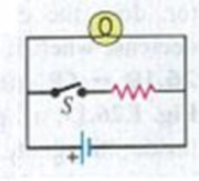
If the battery in Discussion Question Q26.10 is ideal with no internal resistance, what will happen to the brightness of the bulb when S is closed? Why?
Figure Q26.10
Expert Solution & Answer
Want to see the full answer?
Check out a sample textbook solution
Students have asked these similar questions
A triangular array of resistors is shown in Fig. E26.5. What current will this array draw from a 35.0-V battery having negligible internal resistance if we connect it across (a) ab; (b) bc; (c) ac? (d) If the battery has an internal resistance of 3.00 Ω, what current will the array draw if the battery is connected across bc?
Each of the six real batteries in the figure below has an emf of 24 V and a resistance of 4.6 Ω.
(a) What is the current through the (external) resistance R = 3.6 Ω? _____________A(b) What is the potential difference across each battery? ___________V(c) What is the power of each battery? ___________W(d) At what rate does each battery transfer energy to internal thermal energy? __________W
(please show the units when working through the problem so that I can follow it easier)
The given pair of capacitors in FigureP18.67 is fully charged by a 12.0 - V battery.The battery is disconnected and the circuitclosed. After 1.00 ms, how much chargeremains on (a) the 3.00 - µF capacitor?(b) The 2.00 - µF capacitor? (c) What is thecurrent in the resistor?
Chapter 26 Solutions
University Physics with Modern Physics (14th Edition)
Ch. 26.1 - Suppose all three of the resistors shown in Fig....Ch. 26.2 - Subtract Eq. (1) from Eq. (2) in Example 26.6. To...Ch. 26.3 - You want to measure the current through and the...Ch. 26.4 - The energy stored in a capacitor is equal to...Ch. 26.5 - To prevent the circuit breaker in Example 26.14...Ch. 26 - In which 120-V light bulb does the filament have...Ch. 26 - Two 120-V light bulbs, one 25-W and one 200-W,...Ch. 26 - You connect a number of identical light bulbs to a...Ch. 26 - In the circuit shown in Fig. Q26.4, three...Ch. 26 - If two resistors R1 and R2 (R2 R1) are connected...
Ch. 26 - If two resistors R1 and R2 (R2 R1) are connected...Ch. 26 - A battery with no internal resistance is connected...Ch. 26 - A resistor consists of three identical metal...Ch. 26 - A light bulb is connected in the circuit shown in...Ch. 26 - A real battery, having nonnegligible internal...Ch. 26 - If the battery in Discussion Question Q26.10 is...Ch. 26 - Consider the circuit shown in Fig. Q26.12. What...Ch. 26 - Is it possible to connect resistors together in a...Ch. 26 - The battery in the circuit shown in Fig. Q26.14...Ch. 26 - In a two-cell flashlight, the batteries are...Ch. 26 - Identical light bulbs A, B, and C are connected as...Ch. 26 - The emf of a flashlight battery is roughly...Ch. 26 - Will the capacitors in the circuits shown in Fig....Ch. 26 - Verify that the time constant RC has units of...Ch. 26 - For very large resistances it is easy to construct...Ch. 26 - When a capacitor, battery, and resistor are...Ch. 26 - A uniform wire of resistance R is cut into three...Ch. 26 - A machine part has a resistor X protruding from an...Ch. 26 - A resistor with R1 = 25.0 is connected to a...Ch. 26 - A 42- resistor and a 20- resistor are connected in...Ch. 26 - A triangular array of resistors is shown in Fig....Ch. 26 - For the circuit shown in Fig. E26.6 both meters...Ch. 26 - For the circuit shown in Fig. E26.7 find the...Ch. 26 - Three resistors having resistances of 1.60 , 2.40...Ch. 26 - Now the three resistors of Exercise 26.8 are...Ch. 26 - Power Rating of a Resistor. The power rating of a...Ch. 26 - In Fig. E26.11, R1, = 3.00 , R2 = 6.00 , and R3=...Ch. 26 - In Fig. E26.11 the battery has emf 35.0 V and...Ch. 26 - Compute the equivalent resistance of the network...Ch. 26 - Compute the equivalent resistance of the network...Ch. 26 - In the circuit of Fig. E26.15, each resistor...Ch. 26 - Consider the circuit shown in Fig. E26.16. The...Ch. 26 - In the circuit shown in Fig. E26.17, the voltage...Ch. 26 - In the circuit shown in Fig. E26.18, = 36.0 V,...Ch. 26 - CP In the circuit in Fig. E26.19, a 20.0- resistor...Ch. 26 - In the circuit shown in Fig. E26.20, the rate at...Ch. 26 - Light Bulbs in Series and in Parallel. Two light...Ch. 26 - Light Bulbs in Series. A 60-W, 120-V light bulb...Ch. 26 - In the circuit shown in Fig. E26.23, ammeter A1...Ch. 26 - The batteries shown in the circuit in Fig. E26.24...Ch. 26 - In the circuit shown in Fig. E26.25 find (a) the...Ch. 26 - Find the emfs 1 and 2 in the circuit of Fig....Ch. 26 - In the circuit shown in Fig. E26.27, find (a) the...Ch. 26 - In the circuit shown in Fig. E26.28, find (a) the...Ch. 26 - The 10.00-V battery in Fig. E26.28 is removed from...Ch. 26 - The 5.00-V battery in Fig. E26.28 is removed from...Ch. 26 - In the circuit shown in Fig. E26.31 the batteries...Ch. 26 - In the circuit shown in Fig. E26.32 both batteries...Ch. 26 - In the circuit shown in Fig. E26.33 all meters are...Ch. 26 - In the circuit shown in Fig. E26.34, the 6.0-...Ch. 26 - The resistance of a galvanometer coil is 25.0 ,...Ch. 26 - The resistance of the coil of a pivoted coil...Ch. 26 - A circuit consists of a series combination of...Ch. 26 - A galvanometer having a resistance of 25.0 has a...Ch. 26 - A capacitor is charged to a potential of 12.0 V...Ch. 26 - You connect a battery, resistor, and capacitor as...Ch. 26 - A 4.60-F capacitor that is initially uncharged is...Ch. 26 - You connect a battery, resistor, and capacitor as...Ch. 26 - CP In the circuit shown in Fig. E26.43 both...Ch. 26 - A 12.4-F capacitor is connected through a 0.895-M...Ch. 26 - An emf source with = 120 V, a resistor with R =...Ch. 26 - A resistor and a capacitor are connected in series...Ch. 26 - CP In the circuit shown in Fig. E26.47 each...Ch. 26 - A 1.50-F capacitor is charging through a 12.0-...Ch. 26 - In the circuit in Fig. E26.49 the capacitors are...Ch. 26 - A 12.0-F capacitor is charged to a potential of...Ch. 26 - In the circuit shown in Fig. E26.51, C = 5.90 F, ...Ch. 26 - Prob. 26.52ECh. 26 - A 1500-W electric beater is plugged into the...Ch. 26 - In Fig. P26.54, the battery has negligible...Ch. 26 - The two identical light bulbs in Example 26.2...Ch. 26 - Each of the three resistors in Fig. P26.56 has a...Ch. 26 - (a) Find the potential of point a with respect to...Ch. 26 - CP For the circuit shown in Fig. P26.58 a 20.0-...Ch. 26 - Calculate the three currents I1, I2, and I3...Ch. 26 - What must the emf in Fig. P26.60 be in order for...Ch. 26 - Find the current through each of the three...Ch. 26 - (a) Find the current through the battery and each...Ch. 26 - Consider the circuit shown in Fig. P26.63. (a)...Ch. 26 - In the circuit shown in Fig. P26.64, = 24.0 V,...Ch. 26 - In the circuit shown in Fig. P26.65, the current...Ch. 26 - In the circuit shown in Fig. P26.66 all the...Ch. 26 - Figure P26.67 employs a convention often used in...Ch. 26 - Three identical resistors are connected in series....Ch. 26 - A resistor R1 consumes electrical power P1 when...Ch. 26 - The capacitor in Fig. F26.70 is initially...Ch. 26 - A 2.00-F capacitor that is initially uncharged is...Ch. 26 - A 6.00-F capacitor that is initially uncharged is...Ch. 26 - Point a in Fig. P26.73 is maintained at a constant...Ch. 26 - The Wheatstone Bridge. The circuit shown in Fig....Ch. 26 - (See Problem 26.67.) (a) What is the potential of...Ch. 26 - A 2.36-F capacitor that is initially uncharged is...Ch. 26 - A 224- resistor and a 589- resistor are connected...Ch. 26 - A resistor with R = 850 is connected to the...Ch. 26 - A capacitor that is initially uncharged is...Ch. 26 - DATA You set up the circuit shown in Fig. 26.22a,...Ch. 26 - DATA You set up the circuit shown in Fig. 26.20....Ch. 26 - DATA The electronics supply company where you work...Ch. 26 - An Infinite Network. As shown in Fig. P26.83, a...Ch. 26 - Suppose a resistor R lies along each edge of a...Ch. 26 - BIO Attenuator Chains and Axons. The infinite...Ch. 26 - Assume that a typical open ion channel spanning an...Ch. 26 - In a simple model of an axon conducting a nerve...Ch. 26 - Cell membranes across a wide variety of organisms...
Additional Science Textbook Solutions
Find more solutions based on key concepts
2. Waves in the Earth and the Ocean
In December 2004, a large earthquake off the coast of Indonesia produced a ...
College Physics: A Strategic Approach (3rd Edition)
Express the unit vectors in terms of (that is, derive Eq. 1.64). Check your answers several ways Also work o...
Introduction to Electrodynamics
13. The hand in FIGURE Q7.13 is pushing on the back of block A. Blocks A and B, with mB > mA, are connected by ...
Physics for Scientists and Engineers: A Strategic Approach with Modern Physics (4th Edition)
The total number of revolution to reach 6.3 rad/s .
Physics (5th Edition)
In which extrasolar planet system(s) (A–D) would we receive light from the star with the largest Doppler shift?...
Lecture- Tutorials for Introductory Astronomy
4.22 The upward normal force exerted by the floor is 620 N on an elevator passenger who weighs 650 N. What are ...
University Physics (14th Edition)
Knowledge Booster


Learn more about
Need a deep-dive on the concept behind this application? Look no further. Learn more about this topic, physics and related others by exploring similar questions and additional content below.Similar questions
- Three 100- resistors are connected as shown in Figure P21.41 The maximum power that can safely be delivered to any one resistor is 25.0 W. (a) What is the maximum potential difference that can be applied to the terminals a and b? (b) For the voltage determined in part (a), what is the power delivered to each resistor? (c) What is the total power delivered to the combination of resistors?arrow_forwardThe ammeter shown in Figure P21.45 reads 2.00 A. Find I1, I2, and . Figure P21.45arrow_forwardThe current-versus-voltage behavior of a certain electrical device is shown in Figure OQ27.9. When the potential difference across the device is 2 V, what is its resistance? (a) 1 (b) 34 (c) (d) undefined (e) none of those answersarrow_forward
- For the network in Figure P18.60, show that the resistance between points a and b is Rab=2717. (Hint: Connect a battery with emf across points a and b and determine /I, where I is the current in the battery.) Figure P18.60arrow_forwardA 200 micro Farad capacitor is charged up by connecting it in series with a 10,000 ohm resistor and a 25 V battery. What is the maximum amount of charge that can be stored on the capacitor in mC?arrow_forwardYou have a circuit and you measure the current and find it is 9.51 micro A. You measure the potential and find it is 5.42 mV. What is the resistance of the resistor?arrow_forward
- If you try and measure the voltage of a battery with a voltmeter connected in series, you won't get a completely accurate measurement because of the internal resistance of the battery. To see how large this effect is, consider trying to measure the terminal voltage of a 1.585 V alkaline cell having an internal resistance of 47 Ω by placing a 0.75 kΩ voltmeter across its terminals. Randomized Variables R = 0.75 kΩr = 47 Ω A. What current flows in A? B. Find the terminal voltage in V. C. To see how close the measured terminal voltage is to the emf (Electro Motive Force), calculate their ratio.arrow_forwardIn the figure below, the ideal batteries have emfs ℰ1 = 12 V, ℰ2 = 6.0 V, and the resistors have resistances R1 = 4.0 Ω and R2 = 5.0 Ω. (a) What is the current in the circuit? _________A(b) What is the dissipation rate in resistor 1? _________W(c) What is the dissipation rate in resistor 2? __________W (please show units when you work this out so that I can follow it easier.)arrow_forwardConsider the two arrangements of batteries and bulbsshown in Figure P18.66. The two bulbs are identical andhave resistance R, and the two batteries are identical withoutput voltage ΔV. (a) In case 1, with the two bulbs in series,compare the brightness of each bulb, the current in eachbulb, and the power delivered to each bulb. (b) In case 2,with the two bulbs in parallel, compare the brightness ofeach bulb, the current in each bulb, and the power suppliedto each bulb. (c) Which bulbs are brighter, those incase 1 or those in case 2? (d) In each case, if one bulb fails,will the other go out as well? If the other bulb doesn’t fail,will it get brighter or stay the same?arrow_forward
- Consider the combination of resistors shown in Figure P18.8. (a) Find the equivalent resistance between point a and b. (b) If a voltage of 35.0 V is applied between points a and b, find the current in each resistor. Figure P18.8arrow_forwardConsider the circuit shown in Figure P21.39. Find (a) the current in the 20.0- resistor and (b) the potential difference between points a and b. Figure P21.39arrow_forwardConsider the combination of resistors shown in Figure P18.8. (a) Find the equivalent resistance between point a and b. (b) If a voltage of 35.0 V is applied between points a and b, find the current in each resistor. Figure P18.8arrow_forward
arrow_back_ios
SEE MORE QUESTIONS
arrow_forward_ios
Recommended textbooks for you
 College PhysicsPhysicsISBN:9781305952300Author:Raymond A. Serway, Chris VuillePublisher:Cengage Learning
 Physics for Scientists and EngineersPhysicsISBN:9781337553278Author:Raymond A. Serway, John W. JewettPublisher:Cengage Learning
 Physics for Scientists and Engineers with Modern ...PhysicsISBN:9781337553292Author:Raymond A. Serway, John W. JewettPublisher:Cengage Learning
 College PhysicsPhysicsISBN:9781285737027Author:Raymond A. Serway, Chris VuillePublisher:Cengage Learning
 Principles of Physics: A Calculus-Based TextPhysicsISBN:9781133104261Author:Raymond A. Serway, John W. JewettPublisher:Cengage Learning
 Physics for Scientists and Engineers: Foundations...PhysicsISBN:9781133939146Author:Katz, Debora M.Publisher:Cengage Learning
College Physics
Physics
ISBN:9781305952300
Author:Raymond A. Serway, Chris Vuille
Publisher:Cengage Learning
Physics for Scientists and Engineers
Physics
ISBN:9781337553278
Author:Raymond A. Serway, John W. Jewett
Publisher:Cengage Learning
Physics for Scientists and Engineers with Modern ...
Physics
ISBN:9781337553292
Author:Raymond A. Serway, John W. Jewett
Publisher:Cengage Learning
College Physics
Physics
ISBN:9781285737027
Author:Raymond A. Serway, Chris Vuille
Publisher:Cengage Learning
Principles of Physics: A Calculus-Based Text
Physics
ISBN:9781133104261
Author:Raymond A. Serway, John W. Jewett
Publisher:Cengage Learning
Physics for Scientists and Engineers: Foundations...
Physics
ISBN:9781133939146
Author:Katz, Debora M.
Publisher:Cengage Learning
How To Solve Any Resistors In Series and Parallel Combination Circuit Problems in Physics; Author: The Organic Chemistry Tutor;https://www.youtube.com/watch?v=eFlJy0cPbsY;License: Standard YouTube License, CC-BY