
Concept explainers
Videos
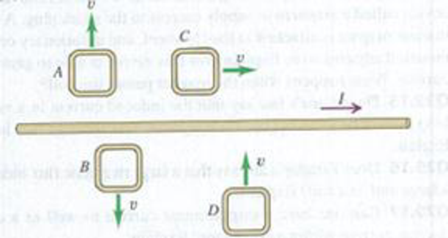
The current I in a long, straight wire is constant and is directed toward the right as in Fig. E29.16.
Figure E29.16
Want to see the full answer?
Check out a sample textbook solution
Chapter 29 Solutions
University Physics, Volume 2 - Technology Update Custom Edition for Texas A&M - College Station, 2/e
Additional Science Textbook Solutions
Physics: Principles with Applications
Tutorials in Introductory Physics
Lecture- Tutorials for Introductory Astronomy
Sears And Zemansky's University Physics With Modern Physics
Conceptual Physical Science (6th Edition)
Cosmic Perspective Fundamentals


- The bar in Figure OQ23.10 moves on rails to the right with a velocity v, and a uniform, constant magnetic field is directed out of the page. Which of the following statements are correct? More than one statement may be correct. (a) The induced current in the loop is zero. (b) The induced current in the loop is clockwise. (c) The induced current in the loop is counterclockwise. (d) An external force is required to keep the bar moving at constant speed. (e) No force is required to keep the bar moving at constant speed.arrow_forwardFigure P23.15 shows a top view of a bar that can slide on two frictionless rails. The resistor is R = 6.00 , and a 2.50-T magnetic field is directed perpendicularly downward, into the paper. Let = 1.20 m. (a) Calculate the applied force required to move the bar to the right at a constant speed of 2.00 m/s. (b) At what rate is energy delivered to the resistor? Figure P23.15 Problems 15 through 18.arrow_forwardA circular coil 15.0 cm in radius and composed of 145 tightly wound turns carries a current of 2.50 A in the counterclockwise direction, where the plane of the coil makes an angle of 15.0 with the y axis (Fig. P30.73). The coil is free to rotate about the z axis and is placed in a region with a uniform magnetic field given by B=1.35jT. a. What is the magnitude of the magnetic torque on the coil? b. In what direction will the coil rotate? FIGURE P30.73arrow_forward
- A wire is bent in the form of a square loop with sides of length L (Fig. P30.24). If a steady current I flows in the loop, determine the magnitude of the magnetic field at point P in the center of the square. FIGURE P30.24arrow_forwardA metal rod of mass m slides without friction along two parallel horizontal rails, separated by a distance and connected by a resistor R, as shown in Figure P30.13. A uniform vertical magnetic field of magnitude B is applied perpendicular to the plane of the paper. The applied force shown in the figure acts only for a moment, to give the rod a speed v. In terms of m, , R, B, and v, find the distance the rod will then slide as it coasts to a stop. Figure P30.13arrow_forwardA metal rod of mass m slides without friction along two parallel horizontal rails, separated by a distance l and connected by a resistor R, as shown in Figure P23.15. A uniform vertical magnetic field of magnitude B is applied perpendicular to the plane of the paper. The applied force shown in the figure acts only for a moment, to give die rod a speed v. In terms of m, l, R, B, and v, find the distance the rod will then slide as it coasts to a stop.arrow_forward
- A toroid has a major radius R and a minor radius r and is tightly wound with N turns of wire on a hollow cardboard torus. Figure P31.6 shows half of this toroid, allowing us to see its cross section. If R r, the magnetic field in the region enclosed by the wire is essentially the same as the magnetic field of a solenoid that has been bent into a large circle of radius R. Modeling the field as the uniform field of a long solenoid, show that the inductance of such a toroid is approximately L=120N2r2R Figure P31.6arrow_forwardA rectangular coil consists of N = 100 closely wrapped turns and has dimensions a = 0.400 m and b = 0.300 m. The coil is hinged along the y axis, and its plane makes an angle = 30.0 with the x axis (Fig. P22.25). (a) What is the magnitude of the torque exerted on the coil by a uniform magnetic field B = 0.800 T directed in the positive x direction when the current is I = 1.20 A in the direction shown? (b) What is the expected direction of rotation of the coil? Figure P22.25arrow_forwardThe homopolar generator, also called the Faraday disk, is a low-voltage, high-current electric generator. It consists of a rotating conducting disk with one stationary brush (a sliding electrical contact) at its axle and another at a point on its circumference as shown in Figure P23.21. A uniform magnetic field is applied perpendicular to the plane of the disk. Assume the field is 0.900 T, the angular speed is 3.20 103 rev/min, and the radius of the disk is 0.400 m. Find the emf generated between the brushes. When superconducting coils are used to produce a large magnetic field, a homopolar generator can have a power output of several megawatts. Such a generator is useful, for example, in purifying metals by electrolysis. If a voltage is applied to the output terminals of the generator, it runs in reverse as a homopolar motor capable of providing great torque, useful in ship propulsion.arrow_forward
- A 500-turn coil with a 0.250m2 area is spun in Earth’s 5.00105T magnetic field, producing a 12.0-kV maximum emf. (a) As what angular velocity must the coil be spun? (b) What is unreasonable about this result? (c) Which assumption or premise is responsible?arrow_forwardA rectangular conducting loop with dimensions w = 32.0 cm and h = 78.0 cm is placed a distance a = 5.00 cm from a long, straight wire carrying current I = 7.00 A in the downward direction (Fig. P32.75). a. What is the magnitude of the magnetic flux through the loop? b. If the current in the wire is increased linearly from 7.00 A to 15.0 A in 0.230 s, what is the magnitude of the induced emf in the loop? c. What is the direction of the current that is induced in the loop during this time interval?arrow_forwardA Figure P32.74 shows an N-turn rectangular coil of length a and width b entering a region of uniform magnetic field of magnitude Bout directed out of the page. The velocity of the coil is constant and is upward in the figure. The total resistance of the coil is R. What are the magnitude and direction of the magnetic force on the coil a. when only a portion of the coil has entered the region with the field, b. when the coil is completely embedded in the field, and c. as the coil begins to exit the region with the field?arrow_forward
 Principles of Physics: A Calculus-Based TextPhysicsISBN:9781133104261Author:Raymond A. Serway, John W. JewettPublisher:Cengage Learning
 Physics for Scientists and Engineers: Foundations...PhysicsISBN:9781133939146Author:Katz, Debora M.Publisher:Cengage Learning
 Physics for Scientists and Engineers with Modern ...PhysicsISBN:9781337553292Author:Raymond A. Serway, John W. JewettPublisher:Cengage Learning
 Physics for Scientists and EngineersPhysicsISBN:9781337553278Author:Raymond A. Serway, John W. JewettPublisher:Cengage Learning