
Videos
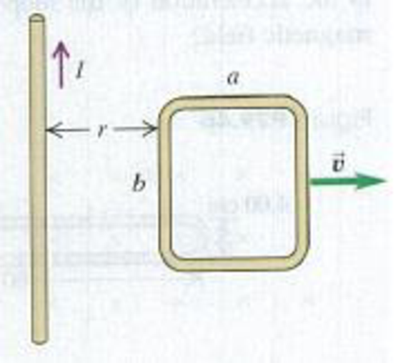
In Fig. P29.51 the loop is being pulled lo the right at constant speed ʋ. A constant current I flows in the long wire, in the direction shown. (a) Calculate the magnitude of the net emf ε induced in the loop. Do this two ways: (i) by using Faraday’s law of induction (Hint: See Exercise 29.7) and (ii) by looking at the emf induced in each segment of the loop due to its motion. (b) Find the direction (clockwise or counterclockwise) of the current induced in the loop. Do this two ways: (i) using Lenz’s law and (ii) using the magnetic force on charges in the loop. (c) Check your answer for the emf in part (a) in the following special cases to see whether it is physically reasonable: (i) The loop is stationary; (ii) the loop is very thin, so a → 0; (iii) the loop gets very far from the wire.
Figure P29.51
Want to see the full answer?
Check out a sample textbook solution
Chapter 29 Solutions
University Physics, Volume 2 - Technology Update Custom Edition for Texas A&M - College Station, 2/e
Additional Science Textbook Solutions
The Cosmic Perspective Fundamentals (2nd Edition)
Physics for Scientists and Engineers: A Strategic Approach, Vol. 1 (Chs 1-21) (4th Edition)
Conceptual Physics (12th Edition)
Physics for Scientists and Engineers: A Strategic Approach with Modern Physics (4th Edition)
Cosmic Perspective Fundamentals
University Physics with Modern Physics (14th Edition)


- Figure P30.39 shows a stationary conductor whose shape is similar to the letter e. The radius of its circular portion is a = 50.0 cm. It is placed in a constant magnetic field of 0.500 T directed out of the page. A straight conducting rod, 50.0 cm long, is pivoted about point O and rotates with a constant angular speed of 2.00 rad/s. (a) Determine the induced emf in the loop POQ. Note that the area of the loop is a2/2. (b) If all the conducting material has a resistance per length of 5.00 /m, what is the induced current in the loop POQ at the instant 0.250 s after point P passes point Q? Figure P30.39arrow_forwardA stiff spring with a spring constant of 1200.0 N/m is connected to a bar on a slide generator as shown in Figure P32.40. Assume the bar has length l = 60.0 cm and mass m = 0.75 kg, and it slides without friction. The bar connects to a U-shaped wire to form a loop that has width w = 40.0 cm and total resistance 25 and that sits in a uniform magnetic field B = 0.35 T. The bar is initially pulled 5.0 cm to the left and released so that it begins to oscillate. What is the induced current in the loop as a function of time, I(t)? (Ignore any effects due to the magnetic force on the oscillating bar.)arrow_forwardThe bar in Figure OQ23.10 moves on rails to the right with a velocity v, and a uniform, constant magnetic field is directed out of the page. Which of the following statements are correct? More than one statement may be correct. (a) The induced current in the loop is zero. (b) The induced current in the loop is clockwise. (c) The induced current in the loop is counterclockwise. (d) An external force is required to keep the bar moving at constant speed. (e) No force is required to keep the bar moving at constant speed.arrow_forward
- A toroid having a rectangular cross section (a = 2.00 cm by b = 3.00 cm) and inner radius R = 4.00 cm consists of N = 500 turns of wire that carry a sinusoidal current I = Imax sin t, with Imax = 50.0 A and a frequency f = /2 = 60.0 Hz. A coil that consists of N = 20 turns of wire is wrapped around one section of the toroid as shown in Figure P30.9. Determine the emf induced in the coil as a function of time. Figure P30.9arrow_forwardReview. Figure P31.31 shows a bar of mass m = 0.200 kg that can slide without friction on a pair of rails separated by a distance = 1.20 m and located on an inclined plane that makes an angle = 25.0 with respect to the ground. The resistance of the resistor is R = 1.00 and a uniform magnetic field of magnitude B = 0.500 T is directed downward, perpendicular to the ground, over the entire region through which the bar moves. With what constant speed v does the bar slide along the rails?arrow_forwardThe magnetic field through a square loop of wire with sides of length 3.00 cm changes with time as shown in Figure P32.8, where the sign indicates the direction of the field relative to the axis of the loop. Plot the emf induced in the loop versus time. FIGURE P32.8arrow_forward
- A square, flat loop of wire is pulled at constant velocity through a region of uniform magnetic field directed perpendicular to the plane of the loop as shown in Figure OQ23.9. Which of the following statements are correct? More than one statement may be correct. (a) Current is induced in the loop in the clockwise direction. (b) Current is induced in the loop in the counterclockwise direction. (c) No current is induced in the loop. (d) Charge separation occurs in the loop, with the top edge positive. (e) Charge separation occurs in the loop, with the top edge negative.arrow_forwardA Figure P32.74 shows an N-turn rectangular coil of length a and width b entering a region of uniform magnetic field of magnitude Bout directed out of the page. The velocity of the coil is constant and is upward in the figure. The total resistance of the coil is R. What are the magnitude and direction of the magnetic force on the coil a. when only a portion of the coil has entered the region with the field, b. when the coil is completely embedded in the field, and c. as the coil begins to exit the region with the field?arrow_forwardIn Figure P30.38, the rolling axle, 1.50 m long, is pushed along horizontal rails at a constant speed v = 3.00 m/s. A resistor R = 0.400 is connected to the rails at points a and b, directly opposite each other. The wheels make good electrical contact with the rails, so the axle, rails, and R form a closed-loop circuit. The only significant resistance in the circuit is R. A uniform magnetic field B = 0.080 0 T is vertically downward. (a) Find the induced current I in the resistor. (b) What horizontal force F is required to keep the axle rolling at constant speed? (c) Which end of the resistor, a or b, is at the higher electric potential? (d) What If? After the axle rolls past the resistor, does the current in R reverse direction? Explain your answer. Figure P30.38arrow_forward
- A conducting rod of length = 35.0 cm is free to slide on two parallel conducting bars as shown in Figure P30.35. Two resistors R1 = 2.00 and R2 = 5.00 are connected across the ends of the bars to form a loop. A constant magnetic field B = 2.50 T is directed perpendicularly into the page. An external agent pulls the rod to the left with a constant speed of v = 8.00 m/s. Find (a) the currents in both resistors, (b) the total power delivered to the resistance of the circuit, and (c) the magnitude of the applied force that is needed to move the rod with this constant velocity. Figure P30.35arrow_forwardA rectangular conducting loop with dimensions w = 32.0 cm and h = 78.0 cm is placed a distance a = 5.00 cm from a long, straight wire carrying current I = 7.00 A in the downward direction (Fig. P32.75). a. What is the magnitude of the magnetic flux through the loop? b. If the current in the wire is increased linearly from 7.00 A to 15.0 A in 0.230 s, what is the magnitude of the induced emf in the loop? c. What is the direction of the current that is induced in the loop during this time interval?arrow_forwardReview. Figure P31.31 shows a bar of mass m that can slide without friction on a pair of rails separated by a distance and located on an inclined plane that makes an angle with respect to the ground. The resistance of the resistor is R. and a uniform magnetic field of magnitude H is directed downward, perpendicular to the ground, over the entire region through which the bar moves. With what constant speed v does the bar slide along the rails?arrow_forward
 Principles of Physics: A Calculus-Based TextPhysicsISBN:9781133104261Author:Raymond A. Serway, John W. JewettPublisher:Cengage Learning
 Physics for Scientists and Engineers with Modern ...PhysicsISBN:9781337553292Author:Raymond A. Serway, John W. JewettPublisher:Cengage Learning
 Physics for Scientists and EngineersPhysicsISBN:9781337553278Author:Raymond A. Serway, John W. JewettPublisher:Cengage Learning
 Physics for Scientists and Engineers: Foundations...PhysicsISBN:9781133939146Author:Katz, Debora M.Publisher:Cengage Learning
 Physics for Scientists and Engineers, Technology ...PhysicsISBN:9781305116399Author:Raymond A. Serway, John W. JewettPublisher:Cengage Learning