
Concept explainers
Videos
DATA You are
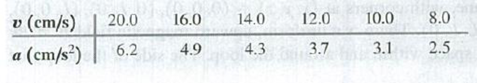
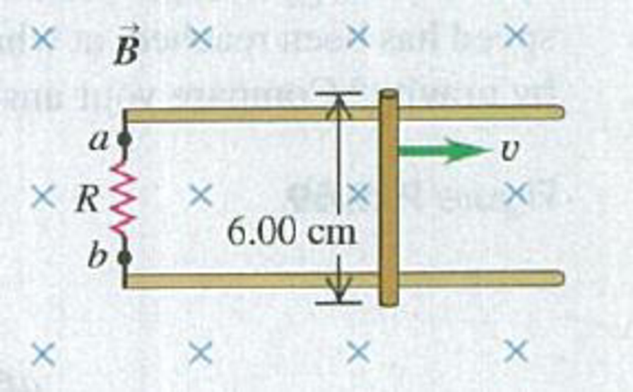
(a) Plot the data as a graph of a versus v. Explain why the data points plotted this way lie close to a straight line, and determine the slope of the best-fit straight line for the data. (b) Use your graph from part (a) to calculate the magnitude B of the magnetic field.(c) While the bar is moving, which end of the resistor, a or b, is at higher potential? (d) How many seconds does it take the speed of the bar to decrease from 20.0 cm/s to 10.0 cm/s?
Figure P29.67
Want to see the full answer?
Check out a sample textbook solution
Chapter 29 Solutions
University Physics, Volume 2 - Technology Update Custom Edition for Texas A&M - College Station, 2/e
Additional Science Textbook Solutions
College Physics
Essential University Physics (3rd Edition)
Essential University Physics: Volume 1 (3rd Edition)
Conceptual Integrated Science
College Physics: A Strategic Approach (3rd Edition)
The Cosmic Perspective (8th Edition)


- A circular coil 15.0 cm in radius and composed of 145 tightly wound turns carries a current of 2.50 A in the counterclockwise direction, where the plane of the coil makes an angle of 15.0 with the y axis (Fig. P30.73). The coil is free to rotate about the z axis and is placed in a region with a uniform magnetic field given by B=1.35jT. a. What is the magnitude of the magnetic torque on the coil? b. In what direction will the coil rotate? FIGURE P30.73arrow_forwardThree long, current-carrying wires are parallel to one another and separated by a distance d. The magnitudes and directions of the currents are shown in Figure P30.91. Wires 1 and 3 are fixed, but wire 2 is free to move. Wire 2 is displaced to the right by a small distance x. Determine the net force (per unit length) acting on wire 2 and the angular frequency of the resulting oscillation. Assume the mass per unit length of wire 2 is and x d. FIGURE P30.91arrow_forwardA piece of insulated wire is shaped into a figure eight as shown in Figure P23.12. For simplicity, model the two halves of the figure eight as circles. The radius of the upper circle is 5.00 cm and that of the lower circle is 9.00 cm. The wire has a uniform resistance per unit length of 3.00 Ω/m. A uniform magnetic field is applied perpendicular to the plane of the two circles, in the direction shown. The magnetic field is increasing at a constant rate of 2.00 T/s. Find (a) the magnitude and (b) the direction of the induced current in the wire. Figure P23.12arrow_forward
- A current-carrying conductor PQ of mass m and length L is placed on an inclined plane with angle of inclination (Fig. P30.93). A uniform magnetic field B is directed upward as shown. Assume friction is negligible. a. Determine the magnitude and direction of the current in the conductor so that it remains in equilibrium. b. If the direction of the current is reversed, will the conductor still be in equilibrium? If not, find the magnitude of the initial acceleration of the conductor. FIGURE P30.93arrow_forwardThe homopolar generator, also called the Faraday disk, is a low-voltage, high-current electric generator. It consists of a rotating conducting disk with one stationary brush (a sliding electrical contact) at its axle and another at a point on its circumference as shown in Figure P23.21. A uniform magnetic field is applied perpendicular to the plane of the disk. Assume the field is 0.900 T, the angular speed is 3.20 103 rev/min, and the radius of the disk is 0.400 m. Find the emf generated between the brushes. When superconducting coils are used to produce a large magnetic field, a homopolar generator can have a power output of several megawatts. Such a generator is useful, for example, in purifying metals by electrolysis. If a voltage is applied to the output terminals of the generator, it runs in reverse as a homopolar motor capable of providing great torque, useful in ship propulsion.arrow_forwardA metal rod of mass m slides without friction along two parallel horizontal rails, separated by a distance l and connected by a resistor R, as shown in Figure P23.15. A uniform vertical magnetic field of magnitude B is applied perpendicular to the plane of the paper. The applied force shown in the figure acts only for a moment, to give die rod a speed v. In terms of m, l, R, B, and v, find the distance the rod will then slide as it coasts to a stop.arrow_forward
- a) At what speed (in m/s) will a proton move in a circular path of the same radius as an electron that travels at 7.75 ✕ 106 m/s perpendicular to the Earth's magnetic field at an altitude where the field strength is 1.25 ✕ 10−5 T? b) What would the radius (in m) of the path be if the proton had the same speed as the electron? c) What would the radius (in m) be if the proton had the same kinetic energy as the electron? and d) What would the radius (in m) be if the proton had the same momentum as the electron?arrow_forwardIn Figure P30.38, the rolling axle, 1.50 m long, is pushed along horizontal rails at a constant speed v = 3.00 m/s. A resistor R = 0.400 is connected to the rails at points a and b, directly opposite each other. The wheels make good electrical contact with the rails, so the axle, rails, and R form a closed-loop circuit. The only significant resistance in the circuit is R. A uniform magnetic field B = 0.080 0 T is vertically downward. (a) Find the induced current I in the resistor. (b) What horizontal force F is required to keep the axle rolling at constant speed? (c) Which end of the resistor, a or b, is at the higher electric potential? (d) What If? After the axle rolls past the resistor, does the current in R reverse direction? Explain your answer. Figure P30.38arrow_forwardWhy is the following situation impossible? A conducting rectangular loop of mass M = 0.100 kg, resistance R = 1.00 , and dimensions w = 50.0 cm by = 90.0 cm is held with its lower edge just above a region with a uniform magnetic field of magnitude B = 1.00 T as shown in Figure P30.34. The loop is released from rest. Just as the top edge of the loop reaches the region containing the field, the loop moves with a speed 4.00 m/s. Figure P30.34arrow_forward
- A metal rod of mass m slides without friction along two parallel horizontal rails, separated by a distance and connected by a resistor R, as shown in Figure P30.13. A uniform vertical magnetic field of magnitude B is applied perpendicular to the plane of the paper. The applied force shown in the figure acts only for a moment, to give the rod a speed v. In terms of m, , R, B, and v, find the distance the rod will then slide as it coasts to a stop. Figure P30.13arrow_forwardA circuit consists of a conducting movable bar and a light bulb connected to two conducting rails as shown in Figure OQ23.16. An external magnetic field is directed perpendicular to the plane of the circuit. Which of the following actions will make the bulb light up? More than one statement may be correct. (a) The bar is moved to the left. (b) The bar is moved to the right. (c) The magnitude of the magnetic field is increased. (d) The magnitude of the magnetic field is decreased. (e) The bar is lifted off the rails.arrow_forward
 Physics for Scientists and EngineersPhysicsISBN:9781337553278Author:Raymond A. Serway, John W. JewettPublisher:Cengage Learning
 Physics for Scientists and Engineers with Modern ...PhysicsISBN:9781337553292Author:Raymond A. Serway, John W. JewettPublisher:Cengage Learning
 Principles of Physics: A Calculus-Based TextPhysicsISBN:9781133104261Author:Raymond A. Serway, John W. JewettPublisher:Cengage Learning
 Physics for Scientists and Engineers: Foundations...PhysicsISBN:9781133939146Author:Katz, Debora M.Publisher:Cengage Learning