
Concept explainers
Videos
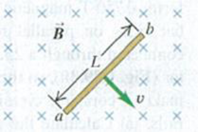
In Fig. E29.25 a
Figure E29.25
Want to see the full answer?
Check out a sample textbook solution
Chapter 29 Solutions
University Physics, Volume 2 - Technology Update Custom Edition for Texas A&M - College Station, 2/e
Additional Science Textbook Solutions
College Physics: A Strategic Approach (3rd Edition)
Conceptual Physical Science (6th Edition)
Introduction to Electrodynamics
College Physics: A Strategic Approach (4th Edition)
Applied Physics (11th Edition)
Physics for Scientists and Engineers: A Strategic Approach, Vol. 1 (Chs 1-21) (4th Edition)


- Review. In studies of the possibility of migrating birds using the Earths magnetic field for navigation, birds have been fitted with coils as caps and collars as shown in Figure P22.39. (a) If the identical coils have radii of 1.20 cm and are 2.20 cm apart, with 50 turns of wire apiece, what current should they both carry to produce a magnetic field of 4.50 105 T halfway between them? (b) If the resistance of each coil is 210 V, what voltage should the battery supplying each coil have? (c) What power is delivered to each coil? Figure P22.39arrow_forwardA rectangular coil consists of N = 100 closely wrapped turns and has dimensions a = 0.400 m and b = 0.300 m. The coil is hinged along the y axis, and its plane makes an angle = 30.0 with the x axis (Fig. P22.25). (a) What is the magnitude of the torque exerted on the coil by a uniform magnetic field B = 0.800 T directed in the positive x direction when the current is I = 1.20 A in the direction shown? (b) What is the expected direction of rotation of the coil? Figure P22.25arrow_forwardA proton moving in the plane of the page has a kinetic energy of 6.00 MeV. A magnetic field of magnitude H = 1.00 T is directed into the page. The proton enters the magnetic field with its velocity vector at an angle = 45.0 to the linear boundary of' the field as shown in Figure P29.80. (a) Find x, the distance from the point of entry to where the proton will leave the field. (b) Determine . the angle between the boundary and the protons velocity vector as it leaves the field.arrow_forward
- A circular coil 15.0 cm in radius and composed of 145 tightly wound turns carries a current of 2.50 A in the counterclockwise direction, where the plane of the coil makes an angle of 15.0 with the y axis (Fig. P30.73). The coil is free to rotate about the z axis and is placed in a region with a uniform magnetic field given by B=1.35jT. a. What is the magnitude of the magnetic torque on the coil? b. In what direction will the coil rotate? FIGURE P30.73arrow_forwardA wire carrying a current I is bent into the shape of an exponential spiral, r = e, from = 0 to = 2 as suggested in Figure P29.47. To complete a loop, the ends of the spiral are connected by a straight wire along the x axis. (a) The angle between a radial line and its tangent line at any point on a curve r = f() is related to the function by tan=rdr/d Use this fact to show that = /4. (b) Find the magnetic field at the origin. Figure P29.47arrow_forwardIn Figure P30.38, the rolling axle, 1.50 m long, is pushed along horizontal rails at a constant speed v = 3.00 m/s. A resistor R = 0.400 is connected to the rails at points a and b, directly opposite each other. The wheels make good electrical contact with the rails, so the axle, rails, and R form a closed-loop circuit. The only significant resistance in the circuit is R. A uniform magnetic field B = 0.080 0 T is vertically downward. (a) Find the induced current I in the resistor. (b) What horizontal force F is required to keep the axle rolling at constant speed? (c) Which end of the resistor, a or b, is at the higher electric potential? (d) What If? After the axle rolls past the resistor, does the current in R reverse direction? Explain your answer. Figure P30.38arrow_forward
- A conducting rod of length = 35.0 cm is free to slide on two parallel conducting bars as shown in Figure P30.35. Two resistors R1 = 2.00 and R2 = 5.00 are connected across the ends of the bars to form a loop. A constant magnetic field B = 2.50 T is directed perpendicularly into the page. An external agent pulls the rod to the left with a constant speed of v = 8.00 m/s. Find (a) the currents in both resistors, (b) the total power delivered to the resistance of the circuit, and (c) the magnitude of the applied force that is needed to move the rod with this constant velocity. Figure P30.35arrow_forwardWhy is the following situation impossible? A conducting rectangular loop of mass M = 0.100 kg, resistance R = 1.00 , and dimensions w = 50.0 cm by = 90.0 cm is held with its lower edge just above a region with a uniform magnetic field of magnitude B = 1.00 T as shown in Figure P30.34. The loop is released from rest. Just as the top edge of the loop reaches the region containing the field, the loop moves with a speed 4.00 m/s. Figure P30.34arrow_forwardA piece of insulated wire is shaped into a figure eight as shown in Figure P23.12. For simplicity, model the two halves of the figure eight as circles. The radius of the upper circle is 5.00 cm and that of the lower circle is 9.00 cm. The wire has a uniform resistance per unit length of 3.00 Ω/m. A uniform magnetic field is applied perpendicular to the plane of the two circles, in the direction shown. The magnetic field is increasing at a constant rate of 2.00 T/s. Find (a) the magnitude and (b) the direction of the induced current in the wire. Figure P23.12arrow_forward
- The homopolar generator, also called the Faraday disk, is a low-voltage, high-current electric generator. It consists of a rotating conducting disk with one stationary brush (a sliding electrical contact) at its axle and another at a point on its circumference as shown in Figure P23.21. A uniform magnetic field is applied perpendicular to the plane of the disk. Assume the field is 0.900 T, the angular speed is 3.20 103 rev/min, and the radius of the disk is 0.400 m. Find the emf generated between the brushes. When superconducting coils are used to produce a large magnetic field, a homopolar generator can have a power output of several megawatts. Such a generator is useful, for example, in purifying metals by electrolysis. If a voltage is applied to the output terminals of the generator, it runs in reverse as a homopolar motor capable of providing great torque, useful in ship propulsion.arrow_forwardA metal rod of mass m slides without friction along two parallel horizontal rails, separated by a distance l and connected by a resistor R, as shown in Figure P23.15. A uniform vertical magnetic field of magnitude B is applied perpendicular to the plane of the paper. The applied force shown in the figure acts only for a moment, to give die rod a speed v. In terms of m, l, R, B, and v, find the distance the rod will then slide as it coasts to a stop.arrow_forwardA metal rod of mass m slides without friction along two parallel horizontal rails, separated by a distance and connected by a resistor R, as shown in Figure P30.13. A uniform vertical magnetic field of magnitude B is applied perpendicular to the plane of the paper. The applied force shown in the figure acts only for a moment, to give the rod a speed v. In terms of m, , R, B, and v, find the distance the rod will then slide as it coasts to a stop. Figure P30.13arrow_forward
 Physics for Scientists and Engineers, Technology ...PhysicsISBN:9781305116399Author:Raymond A. Serway, John W. JewettPublisher:Cengage Learning
 Physics for Scientists and Engineers with Modern ...PhysicsISBN:9781337553292Author:Raymond A. Serway, John W. JewettPublisher:Cengage Learning
 Physics for Scientists and EngineersPhysicsISBN:9781337553278Author:Raymond A. Serway, John W. JewettPublisher:Cengage Learning
 Physics for Scientists and Engineers: Foundations...PhysicsISBN:9781133939146Author:Katz, Debora M.Publisher:Cengage Learning
 Principles of Physics: A Calculus-Based TextPhysicsISBN:9781133104261Author:Raymond A. Serway, John W. JewettPublisher:Cengage Learning