
Videos
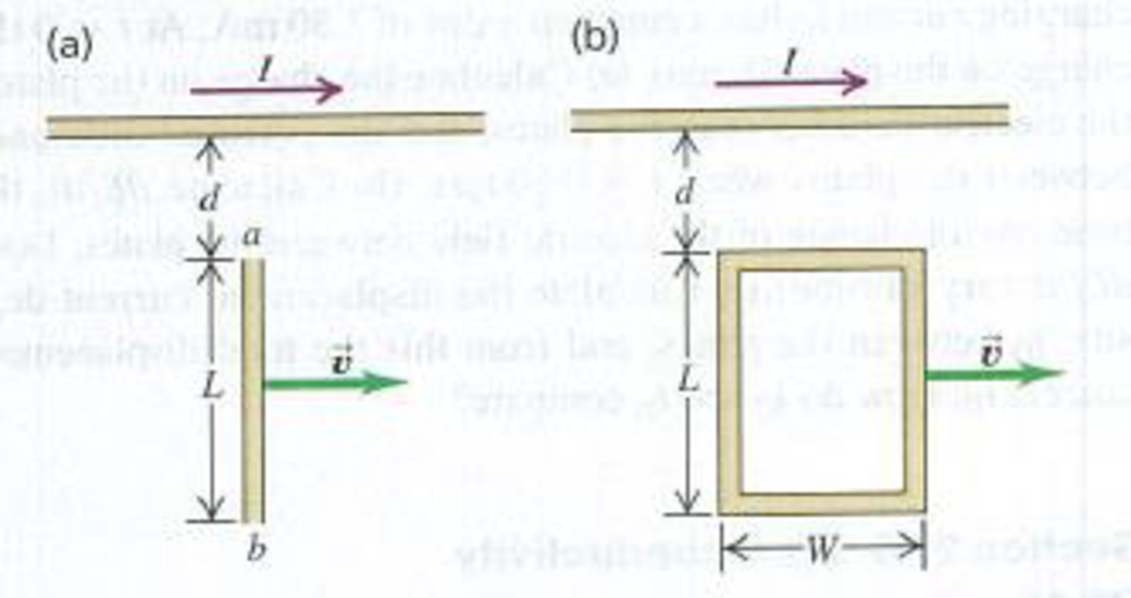
CALC The long, straight wire shown in Fig. P29.57a carries constant current I. A metal bar with length L is moving at constant velocity
Figure P29.57
Want to see the full answer?
Check out a sample textbook solution
Chapter 29 Solutions
University Physics, Volume 2 - Technology Update Custom Edition for Texas A&M - College Station, 2/e
Additional Science Textbook Solutions
College Physics
Essential University Physics: Volume 2 (3rd Edition)
University Physics Volume 1
Physics (5th Edition)
Physics for Scientists and Engineers with Modern Physics
University Physics with Modern Physics (14th Edition)


- A loop of wire in the shape of a rectangle of width w and length L and a long, straight wire carrying a current I lie on a tabletop as shown in Figure P23.7. (a) Determine the magnetic flux through the loop due to the current I. (b) Suppose the current is changing with time according to I = a + bt, where a and b are constants. Determine the emf that is induced in the loop if b = 10.0 A/s, h = 1.00 cm, w = 10.0 cm, and L = 1.00 m. (c) What is the direction of the induced current in the rectangle? Figure P23.7arrow_forwardFigure P23.58 is a graph of the induced emf versus time for a coil of N turns rotating with angular speed ω in a uniform magnetic field directed perpendicular to the coil’s axis of rotation. What If? Copy this sketch (on a larger scale) and on the same set of axes show the graph of emf versus t (a) if the number of turns in the coil is doubled, (b) if instead the angular speed is doubled, and (c) if the angular speed is doubled while the number of turns in the coil is halved. Figure P23.58arrow_forwardA Figure P32.74 shows an N-turn rectangular coil of length a and width b entering a region of uniform magnetic field of magnitude Bout directed out of the page. The velocity of the coil is constant and is upward in the figure. The total resistance of the coil is R. What are the magnitude and direction of the magnetic force on the coil a. when only a portion of the coil has entered the region with the field, b. when the coil is completely embedded in the field, and c. as the coil begins to exit the region with the field?arrow_forward
- A rectangular conducting loop with dimensions w = 32.0 cm and h = 78.0 cm is placed a distance a = 5.00 cm from a long, straight wire carrying current I = 7.00 A in the downward direction (Fig. P32.75). a. What is the magnitude of the magnetic flux through the loop? b. If the current in the wire is increased linearly from 7.00 A to 15.0 A in 0.230 s, what is the magnitude of the induced emf in the loop? c. What is the direction of the current that is induced in the loop during this time interval?arrow_forwardThe magnetic field through a square loop of wire with sides of length 3.00 cm changes with time as shown in Figure P32.8, where the sign indicates the direction of the field relative to the axis of the loop. Plot the emf induced in the loop versus time. FIGURE P32.8arrow_forwardReview. Figure P31.31 shows a bar of mass m = 0.200 kg that can slide without friction on a pair of rails separated by a distance = 1.20 m and located on an inclined plane that makes an angle = 25.0 with respect to the ground. The resistance of the resistor is R = 1.00 and a uniform magnetic field of magnitude B = 0.500 T is directed downward, perpendicular to the ground, over the entire region through which the bar moves. With what constant speed v does the bar slide along the rails?arrow_forward
- Figure P30.39 shows a stationary conductor whose shape is similar to the letter e. The radius of its circular portion is a = 50.0 cm. It is placed in a constant magnetic field of 0.500 T directed out of the page. A straight conducting rod, 50.0 cm long, is pivoted about point O and rotates with a constant angular speed of 2.00 rad/s. (a) Determine the induced emf in the loop POQ. Note that the area of the loop is a2/2. (b) If all the conducting material has a resistance per length of 5.00 /m, what is the induced current in the loop POQ at the instant 0.250 s after point P passes point Q? Figure P30.39arrow_forwardA thin wire = 30.0 cm long is held parallel to and d = 80.0 cm above a long, thin wire carrying I = 200 A and fixed in position (Fig. P30.47). The 30.0-cm wire is released at the instant t = 0 and falls, remaining parallel to the current-carrying wire as it falls. Assume the falling wire accelerates at 9.80 m/s2. (a) Derive an equation for the emf induced in it as a function of time. (b) What is the minimum value of the emf? (c) What is the maximum value? (d) What is the induced emf 0.300 s after the wire is released? Figure P30.47arrow_forwardThe bar in Figure OQ23.10 moves on rails to the right with a velocity v, and a uniform, constant magnetic field is directed out of the page. Which of the following statements are correct? More than one statement may be correct. (a) The induced current in the loop is zero. (b) The induced current in the loop is clockwise. (c) The induced current in the loop is counterclockwise. (d) An external force is required to keep the bar moving at constant speed. (e) No force is required to keep the bar moving at constant speed.arrow_forward
- A rectangular toroid with inner radius R1= 7.0cm, outer radius R2= 9.0cm, height h = 3.0, and N=3.0, and N = 3000 turns is filled with an iron core a magnetic susceptibility 5.2 × 10³. (a) What is the self-inductance of the toroid? (b) If the current through the toroid is 2.0 A, what is the magnetic field at the center of the core? (c) For this same 2.0-A current, what is the effective surface current formed by the aligned atomic current loops in the iron core?arrow_forwardA conducting rod of length moves with velocity v parallel to a long wire carrying a steady current I. The axis of the rod is maintained perpendicular to the wire with the near end a distance r away (Fig. P30.44). Show that the magnitude of the emf induced in the rod is E=0Iv2ln(1+lr) Figure P30.44arrow_forwardA bar magnet is held in a vertical orientation above a loop of wire that lies in the horizontal plane as shown in Figure OQ23.13. The south end of the magnet is toward the loop. After the magnet is dropped, what is true of the induced current in the loop as viewed from above? (a) It is clockwise as the magnet falls toward the loop. (b) It is counterclockwise as the magnet falls toward the loop. (c) It is clockwise after the magnet has moved through the loop and moves away from it. (d) It is always clockwise. (e) It is first counterclockwise as the magnet approaches the loop and then clockwise after it has passed through the loop.arrow_forward
 Principles of Physics: A Calculus-Based TextPhysicsISBN:9781133104261Author:Raymond A. Serway, John W. JewettPublisher:Cengage Learning
 Physics for Scientists and Engineers with Modern ...PhysicsISBN:9781337553292Author:Raymond A. Serway, John W. JewettPublisher:Cengage Learning
 Physics for Scientists and EngineersPhysicsISBN:9781337553278Author:Raymond A. Serway, John W. JewettPublisher:Cengage Learning
 Physics for Scientists and Engineers: Foundations...PhysicsISBN:9781133939146Author:Katz, Debora M.Publisher:Cengage Learning
 College PhysicsPhysicsISBN:9781305952300Author:Raymond A. Serway, Chris VuillePublisher:Cengage Learning