Videos
(a)
ToShow:
The trap filter acts to reject signals in a band of frequencies centered
(a)
Answer to Problem 55P
The trap filter acts to reject signals in a band of frequencies centered at
Explanation of Solution
Given:
The given diagram is shown below
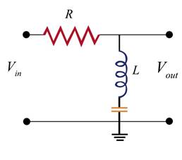
The above circuit is a trap filter circuit. Its phasors diagram is shown below.
Calculation:
The phasor diagram for the trap filter is shown below.
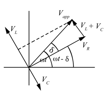
Here
The projection of
Define bandwidth as
Here,
And
Output voltage
Here,
And
Now,
Substitute
Again substitute
Now,
Substitute 0 for
Conclusion:
Hence, it is shown that the trap filter acts to reject signals in a band of frequencies centered at
(b)
The way, the width of the frequency band rejected depends on the resistance
(b)
Answer to Problem 55P
The width of the frequency band rejected is directly proportional to the resistance.
Explanation of Solution
Given:
The given circuit diagram is shown below

The given circuit is a trap filter circuit. Its phasors diagram is shown below.
Calculation:
The required Phasor diagram is shown below
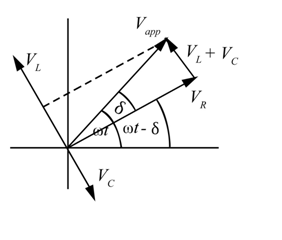
Here
The projection of
Define bandwidth as
And impedance of the trap as
These two will yield an expression for the bandwidth and reveal its dependence on R.
Substitute
Again,
Substitute
For
For the case,
Substitute
Conclusion:
Hence, the width of the frequency band rejected directly proportional to the resistance.
Want to see more full solutions like this?
Chapter 29 Solutions
Physics For Scientists And Engineers Student Solutions Manual, Vol. 1


- At s1iat frequency is the reactance of a 20F capacitor equal to that of a 10-mH inductor?arrow_forwardIn an LC circuit, what determines the frequency and the amplitude of the energy oscillations in either the inductor or capacitor?arrow_forwardWhat is the self-inductance of an LC circuit that oscillates at 60 Hz 1ien the capacitance is 10 F ?arrow_forward
- The voltage across a parallel-plate capacitor with area A=800cm2 and separation d = 2 mm varies sinusoidally as V = (15 mV) cos (150t), where t is in seconds. Find the displacement current between the plates.arrow_forwardThe two circuits shown below act as crude low-pass filters. The input voltage to the circuits is vin, and the output voltage is vout. (a) Show that for the capacitor circuit, voutvin=11+2R2C2 and for the inductor circuit, voutvin=RR2+2L2 (b) Slow that for low frequencies, voutvin , but for high frequencies, vout0 .arrow_forwardCalculate the resonant angular freqency of an RLC series circuit for which R=20 , L=75mH, and C=4.0F , (b) If R is changed to 300, what happens to the resonant angular frequency?arrow_forward
- In an oscillating LC circuit, the maximum charge on the capacitor is qm. Determine the charge on the capacitor and the current through the inductor den energy is shared equally between the electric and magnetic fields. Express your answer in terms of qm, L, and C.arrow_forwardA steady current flows through a circuit with a large induct3ve time constant. When a switch in the circuit is opened, a large spark across the terminals of the switch. Explain.arrow_forwardThe AM band extends from approximately 500. kHz to1 600. kHz. If a 2.0 - µH inductor is used in a tuning circuit fora radio, what are the extremes that a capacitor must reach tocover the complete band of frequencies?arrow_forward
- can someone please explain to me how a dynamic microphone involves magnetic flux and faradays law in its functionality?arrow_forwardConsider a power plant located 25 km outside a towndelivering 50 MW of power to the town. The transmissionlines are made of aluminum cables with a 7 cm2crosssectional area. Find the loss of power in the transmissionlines if it is transmitted at (a) 200 kV (rms) and (b) 120 V(rms).arrow_forward

 Classical Dynamics of Particles and SystemsPhysicsISBN:9780534408961Author:Stephen T. Thornton, Jerry B. MarionPublisher:Cengage Learning