
Concept explainers
Videos
Define the following examples as path, motion, or function generation cases.
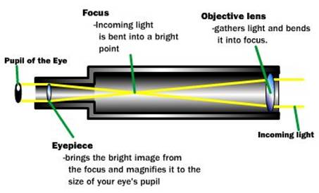
- A telescope aiming (star tracking)
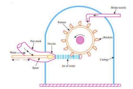
mechanism - A backhoe bucket control mechanism
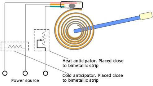
- A thermostat adjusting mechanism
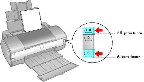
- A computer printer head moving mechanism
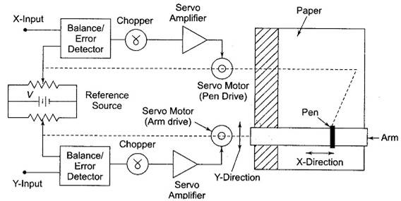
- An XY plotter pen control mechanism
a.
To define:The following examples of telescope aimingcases study given in the problem.
Explanation of Solution
Given information:
The case study of the initial conditions is given that about a telescope aiming or star tracking mechanism.
Calculation:
A telescope aiming or star tracking mechanism that shows a path generation. A star goes along the sky with a
The working mechanism in the line diagram is shown below.
b.
To define: The following examples bucket control arrangement case study given in the problem.
Explanation of Solution
Given information:
The case study of the initial conditions is given that about a telescope aiming or star tracking mechanism.
Calculation:
This is motion generation mainly todigging a trench, say; the location and bucket alignment must becontrolled.
The working mechanism in the line diagram is shown below.
c.
To Define:The following example of thermostat adjusting mechanism case study given in the problem.
Explanation of Solution
This thermostat adjusting mechanism shows a Function generation.Here the output is a chosen function of input over input range.
The working mechanism in the line diagram is shown below.
d.
ToDefine:The following example of the computer printing head moving mechanism case study given in the problem.
Explanation of Solution
Here a moving mechanism of a computer printing head shows path generation and head to be point on a path.
The working mechanism in the line diagram is shown below.
e.
To find:The following examplesof XY plotter pen control mechanism cases study given in the problem.
Explanation of Solution
Here a control mechanism that having an xy plotter pen shows a Path generation and here a pen goes a straight line from point to point.
The working mechanism in the line diagram is shown below.
Want to see more full solutions like this?
Chapter 3 Solutions
DESIGN OF MACHINERY (LL W/ CONNECT)


- LESSON is Transfer Function: Mechanical System - Rotational Movement SUBJECT: FEEDBACK CONTROL SYSTEM Box the final answerarrow_forward1-Draw a figure that shows a negative rotation of a vector in 2D to illustrateyour answer to part (B-3)?2-In technical terms, what does Robot Manipulator Configuration mean? Note/ B-3 In which direction are rotations considered negative and state the handrule for this measurement?arrow_forward1.n which direction are rotations considered positive?2.Draw a figure that shows a positive rotation of a vector in 2D to illustrate your answer to part (B-3)?3.In technical terms, what does Robot Manipulator Configuration mean?arrow_forward
- Explain the difference between forward and inverse kinematics problems.Using geometrical relations derive the forward kinematics of the manipulatorarrow_forwardFor a 1-degree-of-freedom robot arm, it is needed to use a DC motor. Draw a blockdiagram for a mechatronic system that controls the position of this robotic arm forgripping objects. Suggest a sensor system and clarify the flow and nature of signals inyour block diagram.arrow_forwardWhat is Mechanism Designarrow_forward
- 6 Identify the system which is unreliable. a. Open loop and closed loop System b. Open loop System c. None of the above d. Closed loop systemarrow_forwardMeans that data concerning the effects of the computers commands are fed back to the computer as an input signal.arrow_forwardList four basic rules for developing a program for a PLC.arrow_forward
 Automotive Technology: A Systems Approach (MindTa...Mechanical EngineeringISBN:9781133612315Author:Jack Erjavec, Rob ThompsonPublisher:Cengage Learning
 Understanding Motor ControlsMechanical EngineeringISBN:9781337798686Author:Stephen L. HermanPublisher:Delmar Cengage Learning