
Concept explainers
Videos
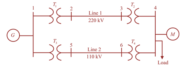
Figure 3.32 shows the oneline diagram of a three-phase power system. By selecting a common base of 100 MVA and 22 kV on the generator side, draw an impedance diagram showing all impedances including the load impedance in per-unit. The data are given a follows:
Lines I and 2 have series reactance’s of 48.4 and

Trending nowThis is a popular solution!

Chapter 3 Solutions
MindTap Engineering, 1 term (6 months) Printed Access Card for Glover/Overbye/Sarma's Power System Analysis and Design, 6th


- Consider a single-phase electric system shown in Figure 3.33. Transformers are rated as follows: XY15MVA,13.8/138kV, leakage reactance 10 YZ15MVA,138/69kV, leakage reactance 8 With the base in circuit Y chosen as 15MVA,138kV determine the per-unit impedance of the 500 resistive load in circuit Z, referred to circuits Z, Y, and X. Neglecting magnetizing currents, transformer resistances, and line impedances, draw the impedance diagram in per unit.arrow_forwardDetermine the positive- and negative-sequence phase shifts for the three- phase transformers shown in Figure 3.36.arrow_forwardConsider the single-Line diagram of a power system shown in Figure 3.42 with equipment ratings given: Generator G1: 50MVA,13.2kV,x=0.15p.u. Generator G2: 20MVA,13.8kV,x=0.15p.u. Three-phase -Y transformer T1: 80MVA,13.2/165YkV,X=0.1p.u. Three-phase Y- transformer T2: 40MVA,165Y/13.8kV,X=0.1p.u. Load: 40MVA,0.8PFlagging,operatingat150kV Choose a base of 100 MVA for the system and 132-kV base in the transmission-line circuit. Let the load be modeled as a parallel combination of resistance and inductance. Neglect transformer phase shifts. Draw a per-phase equivalent circuit of the system showing all impedances in per unit.arrow_forward
- Consider three ideal single-phase transformers (with a voltage gain of ) put together as three-phase bank as shown in Figure 3.35. Assuming positive-sequence voltages for Va,Vb, and Vc find Va,Vb, and VC. in terms of Va,Vb, and Vc, respectively. (a) Would such relationships hold for the line voltages as well? (b) Looking into the current relationships, express IaIb and Ic in terms of IaIb and Ic respectively. (C) Let S and S be the per-phase complex power output and input. respectively. Find S in terms of S.arrow_forwardIn the system shown in Figure 1, the transformers are connected star-star with both star points grounded and the generator is connected in star with its star points grounded. The per unit impedances of each element on a 40 MVA base are given in Table 1 and the voltage levels are given in Table 2. Z [p.u.] 0 2 tööt Generator 0.01 +j0.08 p.u. L Figure 1: A section of the distribution system Transformer T1 Line V BASE [KV] 0.04 + j 0.03 + j 0.15000000000000002 0.06000000000000000 Generator Table 1: Sequence impedances (p.u. on 40 MVA base) 3 T2 181. Line 3 10 Table 2: Voltage bases (kV) Load 1 Transformer T2 Load Current A load current of 11.316 kA is flowing with a lagging power factor of 90 %. Convert this to a current vector in per-unit. IL = 0.04 + j 0.06000000000000000arrow_forwardQ2) A 13.2-kV single-phase generator supplies power to a load through a transmission line. The load's impedance is Zload = 500 236.87° ohm, and the transmission line's impedance is Zline = 60 253.1° ohm. To reduce transmission line losses to 0.0103 of its losses without using the transformers design and use two transformers T1 between the generator and the transmission line and T2 between the transmission line and the load.arrow_forward
- Connect three single-phase transformers in Y-Y, with subtractive polarity, so that the line-to-line voltages on the primary are 30 degrees delayed to their respective line-to-line voltages on the secondary. It should show each step that is needed to make this connection (example: the phasor diagram) and should show the final connection of the three transformers including the polarity markings. Assume phase A on the primary is terminal "H1".arrow_forward1. A single-phase power system as shown in Figure 1 consists of a 240 V, 60 Hz generator supplying a load, Zod = 8 + j6 Q through a transmission line of impedance, Zne = 0.08 + j0.14 Q. Answer the following questions: (1) transformer, T; and T2. Determine the voltage at the load and transmission line losses without the (ii) Determine the voltage at the load and transmission line losses with the transformer, T, and T2. T1 T2 1:10 10:1 IG Zaine Zioad source Figure 1arrow_forwardQ2) A 13.2-kV single-phase generator supplies power to a load through a transmission line. The load's impedance is Ztoad 500 236.87° ohm , and the transmission line's impedance is Zine = 60 253.1° ohm. To reduce transmission line losses to 0.0103 of its losses without using the transformers design and use two transformers T1 between the generator and the transmission line and T2 between the transmission line and the load.arrow_forward
- The reactance of a generator is given as 0.25 per-unit based on the generator’s of 18 kV, 500 MVA. Find its per-unit reactance on a base of 20 kV, 100 MVA. a. 0.0505 b. 0.0605 c. 0.0405 d. 0.0606arrow_forwardThe reactance of a generator is given as 0.1 pu based on the generator of 17 KV, 300 MVA. Determine the pu reactance on a base of 17 KV, 250 MVA. New pu reactance is.......arrow_forwardFor the same alternator, the ratio of rated KVA, when connected as 3-phase winding to when connected as single phase alternator (by utilizing the coils) is, a.1.33 b.0.50 c.0.67 d.1.50arrow_forward
 Power System Analysis and Design (MindTap Course ...Electrical EngineeringISBN:9781305632134Author:J. Duncan Glover, Thomas Overbye, Mulukutla S. SarmaPublisher:Cengage Learning