
Concept explainers
Videos
With the same transformer banks as in Problem 3.47, Figure 3.41 shows the oneline diagram of a generator, a step-up transformer bank, a transmission line, a stepown transformer bank, and an impedan load. The generator terminal voltage is 15 kV (line-to-line).
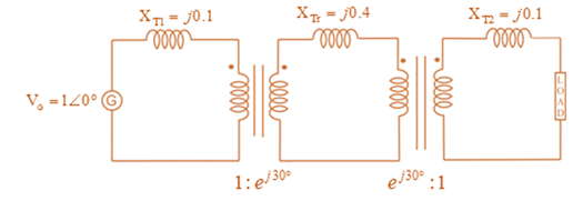
(a) Draw the per-phase equivalent circuit, aounting for phase shifts for positive-sequence operation.
(b) By choosing the line-to-neutral generator terminal voltage as the reference, determine the magnitudes of the generator current, transmiss ion-line current, load current, and line-to-line load voltage. Also, find the three-phase complex power delivered to the load.
Want to see the full answer?
Check out a sample textbook solution
Chapter 3 Solutions
MindTap Engineering, 1 term (6 months) Printed Access Card for Glover/Overbye/Sarma's Power System Analysis and Design, 6th


- In developing per-unit circuits of systems such as the one shown in Figure 3.10. when moving across a transformer, the voltage base is changed in proportion to the transformer voltage ratings. (a) True (b) Falsearrow_forwardConsider three ideal single-phase transformers (with a voltage gain of ) put together as three-phase bank as shown in Figure 3.35. Assuming positive-sequence voltages for Va,Vb, and Vc find Va,Vb, and VC. in terms of Va,Vb, and Vc, respectively. (a) Would such relationships hold for the line voltages as well? (b) Looking into the current relationships, express IaIb and Ic in terms of IaIb and Ic respectively. (C) Let S and S be the per-phase complex power output and input. respectively. Find S in terms of S.arrow_forwardThe per-unit equivalent circuit of two transformers Ta and Tb connected in parallel, with the same nominal voltage ratio and the same reactan of 0.1 per unit on the same base, is shown in Figure 3.43. Transformer Tb has a voltage-magnitude step-up toward the load of 1.05 times that of Ta (that is, the tap on the secondary winding of Tb is set to 1.05). The load is represented by 0.8+j0.6 per unit at a voltage V2=1.0/0 per unit. Determine the complex power in per unit transmitted to the load through each transformer, comment on how the transformers share the real and reactive powers.arrow_forward
- Three single-phase two-winding transformers, each rated 25MVA,54.2/5.42kV, are connected to form a three-phase Y- bank with a balanced Y-connected resistive load of 0.6 per phase on the low-voltage side. By choosing a base of 75 MVA (three phase) and 94 kV (line-to-line) for the high-voltage side of the transformer bank, specify the base quantities for the low-voltage side. Determine the per-unit resistance of the load on the base for the low-voltage side. Then determine the load resistance RL in ohms referred to the high-voltage side and the per-unit value of this load resistance on the chosen base.arrow_forwardThree single-phase, two-winding transformers, each rated 450MVA,20kV/288.7kV, with leakage reactance Xeq=0.10perunit, are connected to form a three-phase bank. The high-voltage windings are connected in Y with a solidly grounded neutral. Draw the per-unit equivalent circuit if the low-voltage windings are connected (a) in with American standard phase shift or (b) in Y with an open neutral. Use the transformer ratings as base quantities. Winding resistances and exciting current are neglected.arrow_forwardFor developing per-unit equivalent circuits of single-phase three-winding transformer, a common Sbase is selected for all three windings and voltage bases are selected in proportion to the rated voltage of the windings (a) True (b) Falsearrow_forward
- Three single-phase two-winding transformers, each rated 3kVA,220/110volts,60Hz, with a 0.10 per-unit leakage reactance, are connected as a three-phase extended autotransformer bank, as shown in Figure 3.36(c). The low-voltage winding has a 110 volt rating. (a) Draw the positive-sequence phasor diagram and show that the high-voltage winding has a 479.5 volt rating. (b) A three-phase load connected to the low-voltage terminals absorbs 6 kW at 110 volts and at 0.8 power factor lagging. Draw the per-unit impedance diagram and calculate the voltage and current at the high-voltage terminals. Assume positive-sequence operation.arrow_forwardConsider Figure 3.4. For an ideal phase-shifting transformer, the imda nce is unchanged when it is referred from one side to the other. (a) True (b) Falsearrow_forwardQ2. (a) Explain what is per unit system? What are the advantages of per-unit computations? Prove for the problem given in part (b) that PU impedance of the circuit element connected by the transformers expressed on a proper base will be same if it is referred to either side of a transformer.arrow_forward
- 3.6 For a conceptual single-phase phase-shifting transformer, the primary voltage leads the secondary voltage by 30°. A load connected to the sec- ondary winding absorbs 110 kVA at an 0.8 power factor leading and at a voltage E, = 277/0° volts. Determine (a) the primary voltage, (b) primary and secondary currents, (c) load impedance referred to the primary wind- ing, and (d) complex power supplied to the primary winding.arrow_forwardAssign the following statements by "Agree", or “Disagree". 1- It is better to use ferrite core instead of iron core in power transformer. 2- The no-load losses are smaller in power transformers as compared with that of the distribution transformers. 3- The core cooling in core-type transformers is better as compared with that of the shell-type. 4- The inrush current can be reduced in transformers by using hard magnetic material core. 5- The inrush current can be reduced in transformers by using soft magnetic material core. 6- The inrush current can be reduced in transformers by using hard magnetic material core with low residual magnetization. 7- The inrush current can be reduced in transformers by using soft magnetic material core with low residual magnetization. 8- Increasing the stacking factor will increase the weight of the transformer. 9- The hysteresis losses is the most effective part of iron losses in transformer. 10- The transformer design procedure is still depending on…arrow_forwardThree zones of a single-phase circuit are identified in Figure. The zones are connected bytransformers T1 and T2, whose ratings are also shown.Using base values of 30 kVA and 240 volts in zone 1:a. draw the per-unit circuit and determine the per-unit impedances and the per-unitsource voltage.b. calculate the load current both in per-unit and in amperes. Transformer windingresistances and shunt admittance branches are neglected.arrow_forward
 Power System Analysis and Design (MindTap Course ...Electrical EngineeringISBN:9781305632134Author:J. Duncan Glover, Thomas Overbye, Mulukutla S. SarmaPublisher:Cengage Learning