
Concept explainers
Videos
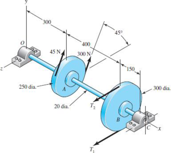
A countershaft carrying two V-belt pulleys is shown in the figure. Pulley A receives power from a motor through a belt with the belt tensions shown. The power is transmitted through the shaft and delivered to the belt on pulley B. Assume the belt tension on the loose side at B is 15 percent of the tension on the Light side.
(a) Determine the tensions in the belt on pulley B, assuming the shaft is running at a constant speed.
(b) Find the magnitudes of the bearing reaction forces, assuming the bearings act as simple supports.
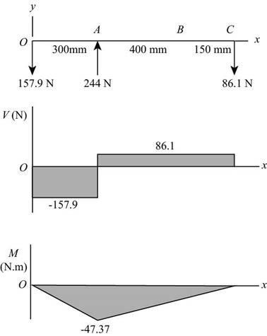
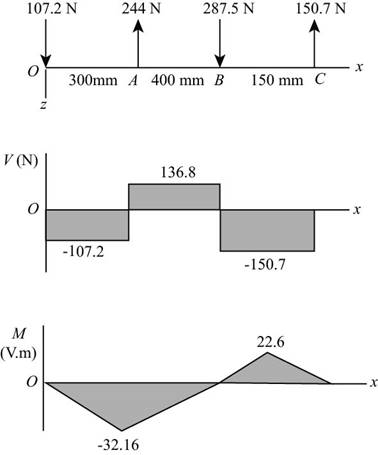
(c) Draw shear-force and bending-moment diagrams for the shaft. If needed, make one set for the horizontal plane and another set for the vertical plane.
(d) At the point of maximum bending moment, determine the bending stress and the torsional shear stress.
(e) At the point of maximum bending moment, determine the principal stresses and the maximum shear stress.
Problem 3–71*
Dimensions in millimeters.
(a)
The tensions in the belt on pulley
Answer to Problem 71P
The tension in the belt pulley
Explanation of Solution
Write the relationship between tension on the loose side with respect to tension on the tight side.
Here, the tension on the tight side is
Write the equation to balance the tension on the counter shaft.
Substitute
Here, the tension on the tight side of pulley
Conclusion:
Substitute
Substitute
Thus, the tension in the belt pulley
(b)
The magnitude of the bearing reaction forces.
Answer to Problem 71P
The magnitude of bearing reaction force at
Explanation of Solution
Write the expression for magnitude of bearing reaction force at
Here, the tension on tight side of pulley
Write the expression for magnitude of bearing reaction force at
Write the expression for magnitude of bearing reaction force at
Here, the magnitude of bearing force at
Write the expression for magnitude of bearing force at
Here, the magnitude of bearing reaction force at
Calculate the bearing reaction force at
Here, the bearing reaction force at
Calculate the bearing reaction force at
Here, the bearing reaction force at
Conclusion:
Substitute
Substitute
Substitute
Substitute
Substitute
Substitute
Thus, the magnitude of bearing reaction force at
(c)
The shear force diagram and bending moment diagram for the shaft.
Answer to Problem 71P
The shear force diagram and bending moment diagram for the shaft in
The shear force diagram and bending moment diagram for the shaft in
Explanation of Solution
The calculations for shear force and bending moment diagram in
Calculate the shear force at
Here, the shear force at
Calculate the shear force at
Here, the shear force at
Calculate the shear force at
Here, the shear force at
Calculate the moment at
The moment at the supports of the simply supported beam is zero.
Calculate the moment at
Here, the moment at
The calculations for shear force and bending moment diagram in
Calculate the shear force at
Here, the shear force at
Calculate the shear force at
Here, the shear force at
Calculate the shear force at
Calculate the shear force at
Here, the shear force at
Calculate the moment at
The moment at the supports of the simply supported beam is zero.
Calculate the moment at
Here, the moment at
Calculate the moment at
Here, the moment at
Conclusion:
Substitute
Substitute
Substitute
Substitute
Thus, the shear force diagram and bending moment diagram for the shaft in

Figure-(1)
Substitute
Substitute
Substitute
Substitute
Substitute
Substitute
Thus, the shear force diagram and bending moment diagram for the shaft in

Figure-(2)
(d)
The bending stress at point of maximum bending moment.
The shear stress at point of maximum bending moment.
Answer to Problem 71P
The bending stress at point of maximum bending moment is
The shear stress at point of maximum bending moment is
Explanation of Solution
It is clear from the bending moment diagrams, that the critical location is at
Write the net moment at
Here, the net moment at
Write the torque transmitted by shaft from
Here, the torque transmitted by shaft from
Calculate the bending stress.
Here, the bending stress is
Calculate the shear stress.
Here, the shear stress is
Conclusion:
Substitute
Substitute
Convert the diameter of the shaft from
Substitute
Thus, the bending stress at point of maximum bending moment is
Substitute
Thus, the shear stress at point of maximum bending moment is
(e)
The principal stresses at point of maximum bending moment.
The maximum shear stress at point of maximum bending moment.
Answer to Problem 71P
The principal stresses at point of maximum bending moment are
The maximum shear stress at point of maximum bending moment is
Explanation of Solution
Calculate the maximum principal stress.
Here, the maximum principal stress is
Calculate the minimum principal stress.
Here, the minimum principal stress is
Calculate the maximum shear stress.
Here, maximum shear stress is
Conclusion:
Substitute
Substitute
The principal stresses at point of maximum bending moment are
Substitute
Thus, the maximum shear stress at point of maximum bending moment is
Want to see more full solutions like this?
Chapter 3 Solutions
Loose Leaf for Shigley's Mechanical Engineering Design Format: LooseLeaf


- The stepped shaft shown in the figure is required to transmit 600 kW of power at 400 rpm. The shaft has a full quarter-circular fillet, and the smaller diameter D1= 100 mm. If the allowable shear stress at the stress concentration is 100 MPa, at what diameter will this stress be reached? Is this diameter an upper or a lower limit on the value of D2?arrow_forwardRepeat Problem 3.3-1, but now use a circular tube with outer diameter d0= 2.5 in. and inner diameter di= 1.5 in.arrow_forwardRepeat Problem 11.2-3 assuming that R= 10 kN · m/rad and L = 2 m.arrow_forward
- A copper tube with circular cross section has length L = 1.25 m, thickness t = 2 mm, and shear modulus of elasticity G = 45 GPa. The bar is designed to carry a 300 N·m torque acting at the ends. If the allowable shear stress is 25 MPa and the allowable angle of twist between the ends is 2.5°, what is the minimum required outer diameter d?arrow_forwardA prospector uses a hand-powered winch (see figure) to raise a bucket of ore in his mine shaft. The axle of the winch is a steel rod of diameter d = 0.625 in. Also, the distance from the center of the axle to the center of the lifting rope is b = 4.0 in, If the weight of the loaded bucket is W = 100 lb, what is the maximum shear stress in the axle due to torsion? If the maximum bucket load is 125 lb and the allowable shear stress in the axle is 9250 psi, what is the minimum permissible axle diameter?arrow_forwardRepeat Problem 10.4-41 for the loading shown in the figure.arrow_forward
- The composite shaft shown in the figure is manufactured by shrink-Fitting a steel sleeve over a brass core so that the two parts act as a single solid bar in torsion. The outer diameters of the two parts are dY= 40 mm for the brass core and d2= 50 mm for the steel sleeve. The shear moduli of elasticity are Gb= 36 GPa for the brass and Gs= 80 GPa for the steel. (a) Assuming that the allowable shear stresses in the brass and steel are rb= 48 MPa and ts= 80 MPa, respectively, determine the maximum permissible torque Tmax that may be applied to the shaft. (b) If the applied torque T = 2500 kN · m, find the required diameter d2so that allowable shear stress t3is reached in the steel.arrow_forwardRepeat Problem 11.3-9. Use two C 150 × 12.2 steel shapes and assume that E = 205 GPa and L = 6 m.arrow_forwardA uniformly tapered aluminum-ally tube AB of circular cross section and length L is fixed against rotation at A and B, as shown in the figure. The outside diameters at the ends are dAand dA.A hollow section of lenth L/2 and constant thickness t = dA/10 is cast into the tube and extends from B half-way toward A. Torque T0is applied at L/2. (a) Find the reactive torques at the supports, TA and TB. Use numerical values as follows: dA = 2.5 in., L = 48., G = 309 × 106 psi, and T0= 40,000 in.-lb. (b) Repeat part (a) if the hollow sections has constant diameter dA.arrow_forward
- Solve the preceding problem if the stress and dimensions aallow = 2450 pai, L = 80 in., b = 2.5 in,, h = 10 in., and d = 2.5 inarrow_forwardA bumping post at the end of a track in a railway yard has a spring constant k = 8.0 MN/m (see figure). The maximum possible displacement d or the end of the striking plate is 450 mm. What is the maximum velocity vmaxthat a railway car of weight W = 545 kN can have without damaging the bumping post when it strikes it?arrow_forwardThe propeller shaft of a large ship has an outside diameter 18 in. and inside diameter 12 in,, as shown in the figure. The shaft is rated for a maximum shear stress of 4500 psi. If the shaft is turning at 100 rpm, what is the maximum horsepower that can be transmitted without exceeding the allowable stress? If the rotational speed of the shaft is doubled but the power requirements remain unchanged, what happens to the shear stress in the shaft?arrow_forward
 Mechanics of Materials (MindTap Course List)Mechanical EngineeringISBN:9781337093347Author:Barry J. Goodno, James M. GerePublisher:Cengage Learning