
Concept explainers
Videos
Repeat Prob. 3–15 for:
(a) σx = 28 MPa, σy = 7 MPa, τxy = 6 MPa cw
(b) σx = 9 MPa, σy = –6 MPa, τxy = 3 MPa cw
(c) σx = –4 MPa, σy = 12 MPa, τxy = 7 MPa ccw
(d) σx = 6 MPa, σy = –5 MPa, τxy = 8 MPa ccw
(a)
The principle normal stress.
The shear stress.
The angle from
Answer to Problem 16P
The principle normal stress
The shear stress is
The angle from
Explanation of Solution
Write the coordinates of the points through which the Mohr’s circle pass.
Here, the stress along x face is
Draw the
Write the formula for the center point.
Here, the center point is
Write the expression for the angle between the line joining points A and B with
Here, the angle made by the diameter with positive x-axis in the counterclockwise direction is
Write the expression of the radius of circle.
Write the expression maximum in plane normal stress.
Here, the maximum in plane normal stress are
Write the expression of maximum in plane shear stress.
Here, the maximum shear stress is
Write the expression for the angle of maximum shear plane.
Here, the angle is
Conclusion:
Substitute the value
Draw the Mohr’s circle diagram.
The Figure (1) shows the Mohr’s circle diagram.
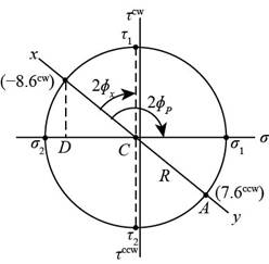
Figure (1)
Substitute the value
Substitute the value
Thus, the angle from
Substitute the value
Substitute the value
Thus, the principle normal stress
Substitute the value
Thus, the principle normal stress
Substitute the value
Thus, the shear stress is
Substitute the value
The Figure (2) shows the maximum in plane normal stress distribution about the plane.
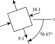
Figure (2)
The Figure (3) shows stress distribution at maximum shear stress plane.
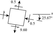
Figure (3)
(b)
The principle normal stress.
The shear stress.
The angle from
Answer to Problem 16P
The principle normal stress
The shear stress is
The angle from
Explanation of Solution
Write the coordinates of the points through which the Mohr’s circle pass.
Draw the
Write the formula for the center point.
Write the expression for the angle between the line joining points A and B with
Write the expression of the radius of circle.
Write the expression maximum in plane normal stress.
Write the expression of maximum in plane shear stress.
Write the expression for the angle of maximum shear plane.
Write the expression for the angle between the line joining points A and B with
Conclusion:
Substitute
Substitute
Draw the Mohr’s circle diagram.
The Figure (4) shows the Mohr’s circle diagram.
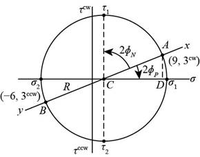
Figure (4)
Substitute the value
Substitute the value
Thus, the angle from
Substitute the value
Substitute
Thus, the principle normal stress
Substitute
Thus, the principle normal stress
Substitute the value
Thus, the shear stress is
Substitute the value
The Figure (5) shows the maximum in plane normal stress distribution about the plane.
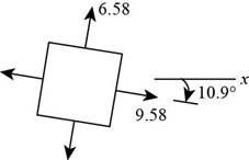
Figure (5)
The Figure (6) shows stress distribution at maximum shear stress plane.
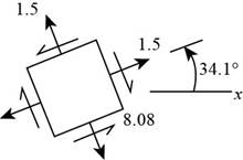
Figure (6)
Thus, the principle normal stress
(c)
The principle normal stress.
The shear stress.
The angle from
Answer to Problem 16P
The principle normal stress
The shear stress is
The angle from
Explanation of Solution
Write the coordinates of the points through which the Mohr’s circle pass.
Draw the
Write the formula for the center point.
Write the expression for the angle between the line joining points A and B with
Write the expression of the radius of circle.
Write the expression maximum in plane normal stress.
Write the expression of maximum in plane shear stress.
Write the expression for the angle of maximum shear plane.
Conclusion:
Substitute the value
Substitute
Draw the Mohr’s circle diagram.
Figure (7) shows the Mohr’s circle diagram.
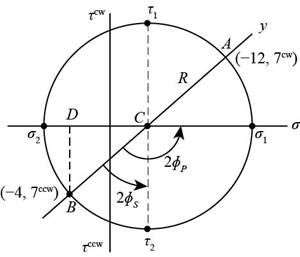
Figure (7)
Substitute the value
Substitute the value
Substitute the value
Substitute the value
Substitute the value
Substitute the value
Substitute the value
The Figure (8) shows the maximum in plane normal stress distribution about the plane.
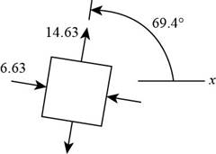
Figure (8)
The Figure (9) shows stress distribution at maximum shear stress plane.
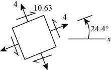
Figure (9)
Thus, the he principle normal stress
(d)
The principle normal stress.
The shear stress.
The angle from
Answer to Problem 16P
The principle normal stress
The shear stress is
The angle from
Explanation of Solution
Write the coordinates of the points through which the Mohr’s circle pass.
Draw the
Write the formula for the center point.
Write the expression for the angle between the line joining points A and B with
Write the expression of the radius of circle.
Write the expression maximum in plane normal stress.
Write the expression of maximum in plane shear stress.
Write the expression for the angle of maximum shear plane.
Write the expression for the angle between the line joining points A and B with
Conclusion:
Substitute
Substitute
Draw the Mohr’s circle diagram.
The Figure (10) shows the Mohr’s circle diagram.
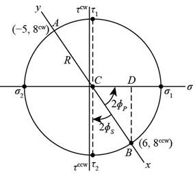
Figure (10)
Substitute the value
Substitute the value
Substitute the value
Substitute the value
Substitute the value
Substitute the value
Substitute the value
The Figure (11) shows the maximum in plane normal stress distribution about the plane.
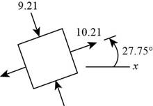
Figure (11)
The Figure (12) shows stress distribution at maximum shear stress plane.
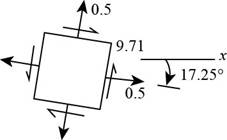
Figure (12)
Thus, the principle normal stress
Want to see more full solutions like this?
Chapter 3 Solutions
Loose Leaf for Shigley's Mechanical Engineering Design Format: LooseLeaf


- Solve the preceding problem if the stress and dimensions aallow = 2450 pai, L = 80 in., b = 2.5 in,, h = 10 in., and d = 2.5 inarrow_forwardA propeller shaft for a small yacht is made of a solid steel bar 104 mm in diameter. The allowable stress in shear is 48 MPa, and the allowable rate of twist is 2.0° in 3.5 meters. (a) Assuming that the shear modulus of elasticity is G = 80 GPa, determine the maximum torque that can be applied to the shaft. (b) Repeat part (a) if the shaft is now hollow with an inner diameter of 5d18. Compare values to corresponding values from part (a).arrow_forwardSolve the preceding problem for a W 200 × 41,7 shape with h = 166 mm, h = 205 mm. rw = 7.24 mm, tE= ILS mm,andV = 38 kN.arrow_forward
- The stepped shaft shown in the figure is required to transmit 600 kW of power at 400 rpm. The shaft has a full quarter-circular fillet, and the smaller diameter D1= 100 mm. If the allowable shear stress at the stress concentration is 100 MPa, at what diameter will this stress be reached? Is this diameter an upper or a lower limit on the value of D2?arrow_forwardA copper tube with circular cross section has length L = 1.25 m, thickness t = 2 mm, and shear modulus of elasticity G = 45 GPa. The bar is designed to carry a 300 N·m torque acting at the ends. If the allowable shear stress is 25 MPa and the allowable angle of twist between the ends is 2.5°, what is the minimum required outer diameter d?arrow_forwardThe hollow drill pipe for an oil well (sec figure) is 6,2 in. in outer diameter and 0.75 in. in thickness. Just above the bit, the compressive force in the pipe (due to the weight of the pipe) is 62 kips and the torque (due to drilling) is 185 kip-in. Determine the maximum tensile, compressive, and shear stresses in the drill pipe.arrow_forward
- Solve the preceding problem if F =90 mm, F = 42 kN, and t = 40°MPaarrow_forwardA tubular shaft being designed for use on a construction site must transmit 120 kW at 1,75 Hz, The inside diameter of the shaft is to be one-half of the outside diameter. If the allowable shear stress in the shaft is 45 MPa, what is the minimum required outside diameter d?arrow_forwardThe propeller shaft of a large ship has an outside diameter 18 in. and inside diameter 12 in,, as shown in the figure. The shaft is rated for a maximum shear stress of 4500 psi. If the shaft is turning at 100 rpm, what is the maximum horsepower that can be transmitted without exceeding the allowable stress? If the rotational speed of the shaft is doubled but the power requirements remain unchanged, what happens to the shear stress in the shaft?arrow_forward
- What is the maximum power that can be delivered by a hollow propeller shaft (outside diameter 50 mm, inside diameter 40 mm, and shear modulus of elasticity 80 GPa) turning at 600 rpm if the allowable shear stress is 100 MPa and the allowable rate of twist is 3.0°/m?arrow_forwardA thin-walled rectangular tube has uniform thickness t and dimensions a x b to the median line of the cross section (see figure). How does the shear stress in the tube vary with the ratio = a/b if the total length Lmof the median line of the cross section and the torque T remain constant? From your results, show that the shear stress is smallest when the tube is square (ß = 1).arrow_forwardTwo sections of steel drill pipe, joined by bolted flange plates at Ä are being tested to assess the adequacy of both the pipes. In the test, the pipe structure is fixed at A, a concentrated torque of 500 kN - m is applied at x = 0.5 m, and uniformly distributed torque intensity t1= 250 kN m/m is applied on pipe BC. Both pipes have the same inner diameter = 200 mm. Pipe AB has thickness tAB=15 mm, while pipe BC has thickness TBC= 12 mm. Find the maximum shear stress and maximum twist of the pipe and their locations along the pipe. Assume G = 75 GPa.arrow_forward
 Mechanics of Materials (MindTap Course List)Mechanical EngineeringISBN:9781337093347Author:Barry J. Goodno, James M. GerePublisher:Cengage Learning