
Concept explainers
Videos
Repeat Prob. 3–8 using singularity functions exclusively (including reactions).
The reaction at the supports.
The shear force diagram.
The bending moment diagram.
Answer to Problem 12P
The reaction force
The reaction force
The reaction force
The shear force diagram is shown is below.

The bending moment diagram is shown below.

Explanation of Solution
The following figure shows the load applied to a beam.
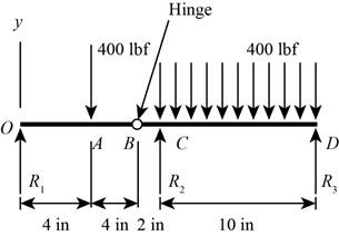
Figure-(1)
Refer to Table 3-1 “Singularity (Macaulay) functions”.
Write the expression for load intensity acting on the beam.
Here, the reaction force at point O is
Write the expression for the shear force.
Here, the net shear force is
Substitute the value from Equation (I) to Equation (II).
Write the expression for the moment.
Here, the net bending moment is
Substitute the value from Equation (III) to Equation (IV).
Conclusion:
Substitute
Thus, the reaction force
Substitute
Substitute
Thus, the reaction force
Substitute
Thus, the reaction force
Substitute the value of
The magnitude of shear force remains constant.
Substitute the value of
At
Substitute
At
Substitute
Similarly for the other values of
The Table-1 shows the variation of moment.
Table-1
Substitute the value of
The magnitude of shear force remains constant.
Substitute the value of
At
Substitute
At
Substitute
Similarly for the other values of
Table-2 shows the variation of moment.
Table-2
Substitute the value of
At
Substitute
At
Substitute
Similarly for the other values of
The Table-3 shows the variation of shear force.
Table-3
Substitute the value of
At
Substitute
At
Substitute
Similarly for the other values of
Differentiate Equation (X).
Equate the above expression to zero to obtain the location of maxima.
The Table-4 shows the variation of moment.
Table-4
The shear force diagram is shown in Figure-(2).
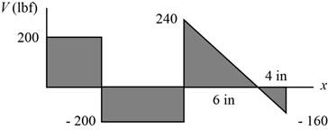
Figure-(2)
The bending moment diagram is shown in Figure-(3).
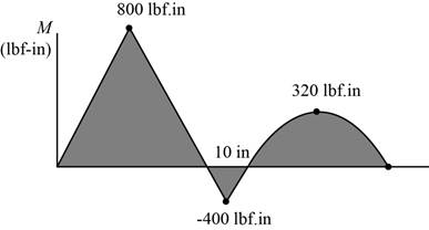
Figure-(3)
Want to see more full solutions like this?
Chapter 3 Solutions
Loose Leaf for Shigley's Mechanical Engineering Design Format: LooseLeaf


- A tubular shaft being designed for use on a construction site must transmit 120 kW at 1,75 Hz, The inside diameter of the shaft is to be one-half of the outside diameter. If the allowable shear stress in the shaft is 45 MPa, what is the minimum required outside diameter d?arrow_forwardA copper tube with circular cross section has length L = 1.25 m, thickness t = 2 mm, and shear modulus of elasticity G = 45 GPa. The bar is designed to carry a 300 N·m torque acting at the ends. If the allowable shear stress is 25 MPa and the allowable angle of twist between the ends is 2.5°, what is the minimum required outer diameter d?arrow_forwardA solid circular bar of steel (G = 78 GPa) transmits a torque T = 360 N - m. The allowable stresses in tension, compression, and shear arc 90 MPa, 70 MPa, and 40 MPa, respectively. Also, the allowable tensile strain is 220 x 10-6, Determine the minimum required diameter d of the bar, If the bar diameter d = 40 mm, what is Tmax?arrow_forward
- A propeller shaft for a small yacht is made of a solid steel bar 104 mm in diameter. The allowable stress in shear is 48 MPa, and the allowable rate of twist is 2.0° in 3.5 meters. (a) Assuming that the shear modulus of elasticity is G = 80 GPa, determine the maximum torque that can be applied to the shaft. (b) Repeat part (a) if the shaft is now hollow with an inner diameter of 5d18. Compare values to corresponding values from part (a).arrow_forwardRepeat Problem 11.3-9. Use two C 150 × 12.2 steel shapes and assume that E = 205 GPa and L = 6 m.arrow_forwardTwo circular aluminum pipes of equal length L = 24 in. arc loaded by torsional moments T (sec figure). Pipe I has outside and inside diameters d2= 3 in. and L2, = 2.5 in., respectively. Pipe 2 has a constant outer diameter of d2along its entire length L and an inner diameter of d1but has an increased inner diameter of d3= 2.65 in. over the middle third. Assume that E = 10,400 ksi, u = 0.33, and allowable shear stress ra= 6500 psi. Find the maximum acceptable torques that can be applied to Pipe 1; repeat for Pipe 2. If the maximum twist e of Pipe 2 cannot exceed 5/4 of that of Pipe 1, what is the maximum acceptable length of the middle segment? Assume both pipes have total length L and the same applied torque T. Find the new value of inner diameter d3of Pipe 2 if the maximum torque carried by Pipe 2 is to be 7/8 of that for Pipe L If the maximum normal strain in each pipe is known to bemax = 811 x 10-6, what is the applied torque on each pipe? Also, what is the maximum twist of each pipe? Use the original properties and dimensions.arrow_forward
- Solve the preceding problem for a W 200 × 41,7 shape with h = 166 mm, h = 205 mm. rw = 7.24 mm, tE= ILS mm,andV = 38 kN.arrow_forwardA statically indeterminate stepped shaft ACE is fixed at ends A and B and loaded by a torque TQat point C (see figure). The two segments of the bar are made of the same material, have lengths L4and LB, and have polar moments of inertia IAand Ipb. Determine the angle of rotation 4>of the cross section at Cby using strain energy. Hint: Use Eq, (3-55b) to determine the strain energy Urn terms of the angle d?. Then equate the strain energy to the work done by the torque to. Compare your result with Eq. (3-52) of Example 3-9.arrow_forwardSolve the preceding problem if the shaft has an outer diameter d2=150 mm and inner diameter d1= 100 mm. Also, the steel has a shear modulus of elasticity G = 75 GPa, and the applied torque is 16 kN ·m.arrow_forward
- A solid copper bar of circular cross section has length L = 1.25 m and shear modulus of elasticity G = 45 GPa. The bar is designed to carry a 250 N · m torque acting at the ends. If the allowable shear stress is 30 M Pa and the allowable angle of twist between the ends is 2.5°, what is the minimum required diameter?arrow_forward-7 Repeat Problem 2.3-5, but n include the weight of the bar. See Table I-I in Appendix I for the weight density of steel.arrow_forwardAn aluminum tube has inside diameter dx= 50 mm, shear modulus of elasticity G = 27 GPa, v = 0.33, and torque T = 4.0 kN · m. The allowable shear stress in the aluminum is 50 MPa, and the allowable normal strain is 900 X 10-6. Determine the required outside diameter d2 Re-compute the required outside diameter d2, if allowable normal stress is 62 MPa and allowable shear strain is 1.7 X 10-3.arrow_forward
 Mechanics of Materials (MindTap Course List)Mechanical EngineeringISBN:9781337093347Author:Barry J. Goodno, James M. GerePublisher:Cengage Learning