
Loose Leaf for Shigley's Mechanical Engineering Design Format: LooseLeaf
10th Edition
ISBN: 9780073399652
Author: BUDYNAS
Publisher: Mcgraw Hill Publishers
expand_more
expand_more
format_list_bulleted
Concept explainers
Videos
Textbook Question
Chapter 3, Problem 84P
The cantilevered bar in the figure is made from a ductile material and is statically loaded with Fy = 250 lbf and Fx = Fz = 0. Analyze the stress situation in the small diameter at the shoulder at the shoulder at A by obtaining the following information.
Problem 3–84*
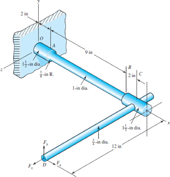
(a) Determine the precise location of the critical stress element at the cross section at A.
(b) Sketch the critical stress element and determine magnitudes and directions for all stresses acting on it. (Transverse shear may be neglected if you can justify this decision.)
(c) For the critical stress element, determine the principal stresses and the maximum shear stress.
Expert Solution & Answer
Want to see the full answer?
Check out a sample textbook solution
Chapter 3 Solutions
Loose Leaf for Shigley's Mechanical Engineering Design Format: LooseLeaf
Ch. 3 - 31 to 34 Sketch a free-body diagram of each...Ch. 3 - 31 to 34 Sketch a free-body diagram of each...Ch. 3 - Sketch a free-body diagram of each element in the...Ch. 3 - 3-1 to 3-4 Sketch a free-body diagram of each...Ch. 3 - 35 to 38 For the beam shown, find the reactions at...Ch. 3 - 35 to 38 For the beam shown, find the reactions at...Ch. 3 - 35 to 38 For the beam shown, find the reactions at...Ch. 3 - For the beam shown, find the reactions at the...Ch. 3 - For the beam shown, find the reactions at the...Ch. 3 - Repeat Prob. 36 using singularity functions...
Ch. 3 - Repeat Prob. 37 using singularity functions...Ch. 3 - Repeat Prob. 38 using singularity functions...Ch. 3 - For a beam from Table A9, as specified by your...Ch. 3 - A beam carrying a uniform load is simply supported...Ch. 3 - For each of the plane stress states listed below,...Ch. 3 - Repeat Prob. 315 for: (a)x = 28 MPa, y = 7 MPa, xy...Ch. 3 - Repeat Prob. 315 for: a) x = 12 kpsi, y = 6 kpsi,...Ch. 3 - For each of the stress states listed below, find...Ch. 3 - Repeat Prob. 318 for: (a)x = 10 kpsi, y = 4 kpsi...Ch. 3 - The state of stress at a point is x = 6, y = 18, z...Ch. 3 - The state of stress at a point is x = 6, y = 18, z...Ch. 3 - Repeat Prob. 320 with x = 10, y = 40, z = 40, xy =...Ch. 3 - A 34-in-diameter steel tension rod is 5 ft long...Ch. 3 - Repeat Prob. 323 except change the rod to aluminum...Ch. 3 - A 30-mm-diameter copper rod is 1 m long with a...Ch. 3 - A diagonal aluminum alloy tension rod of diameter...Ch. 3 - Repeat Prob. 326 with d = 16 mm, l = 3 m, and...Ch. 3 - Repeat Prob. 326 with d = 58 in, l = 10 ft, and...Ch. 3 - Electrical strain gauges were applied to a notched...Ch. 3 - Repeat Prob. 329 for a material of aluminum. 3-29...Ch. 3 - The Roman method for addressing uncertainty in...Ch. 3 - Using our experience with concentrated loading on...Ch. 3 - The Chicago North Shore Milwaukee Railroad was an...Ch. 3 - For each section illustrated, find the second...Ch. 3 - 3-35 to 3-38 For the beam illustrated in the...Ch. 3 - 3-35 to 3-38 For the beam illustrated in the...Ch. 3 - 3-35 to 3-38 For the beam illustrated in the...Ch. 3 - 3-35 to 3-38 For the beam illustrated in the...Ch. 3 - The figure illustrates a number of beam sections....Ch. 3 - A pin in a knuckle joint canning a tensile load F...Ch. 3 - Repeat Prob. 3-40 for a = 6 mm, b = 18 mm. d = 12...Ch. 3 - For the knuckle joint described in Prob. 3-40,...Ch. 3 - The figure illustrates a pin tightly fitted into a...Ch. 3 - For the beam shown, determine (a) the maximum...Ch. 3 - A cantilever beam with a 1-in-diameter round cross...Ch. 3 - Consider a simply supported beam of rectangular...Ch. 3 - In Prob. 346, h 0 as x 0, which cannot occur. If...Ch. 3 - 348 and 349 The beam shown is loaded in the xy and...Ch. 3 - The beam shown is loaded in the xy and xz planes....Ch. 3 - Two steel thin-wall tubes in torsion of equal...Ch. 3 - Consider a 1-in-square steel thin-walled tube...Ch. 3 - The thin-walled open cross-section shown is...Ch. 3 - 3-53 to 3-55 Using the results from Prob. 3-52,...Ch. 3 - 3-53 to 3-55 Using the results from Prob. 3-52,...Ch. 3 - 3-53 to 3-55 Using the results from Prob. 3-52,...Ch. 3 - Two 300-mm-long rectangular steel strips are...Ch. 3 - Using a maximum allowable shear stress of 70 Mpa,...Ch. 3 - Repeat Prob. 357 with an allowable shear stress of...Ch. 3 - Using an allowable shear stress of 50 MPa,...Ch. 3 - A 20-mm-diameter steel bar is to be used as a...Ch. 3 - A 2-ft-long steel bar with a 34-in diameter is to...Ch. 3 - A 40-mm-diameter solid steel shaft, used as a...Ch. 3 - Generalize Prob. 3-62 for a solid shaft of...Ch. 3 - A hollow steel shaft is to transmit 4200 N m of...Ch. 3 - The figure shows an endless-bell conveyor drive...Ch. 3 - The conveyer drive roll in the figure for Prob....Ch. 3 - Consider two shafts in torsion, each of the same...Ch. 3 - 3-68 to 3-71 A countershaft two V-belt pulleys is...Ch. 3 - 3-68 to 3-71 A countershaft two V-belt pulleys is...Ch. 3 - 3-68 to 3-71 A countershaft two V-belt pulleys is...Ch. 3 - A countershaft carrying two V-belt pulleys is...Ch. 3 - A gear reduction unit uses the countershaft shown...Ch. 3 - Prob. 73PCh. 3 - Prob. 74PCh. 3 - Prob. 75PCh. 3 - Prob. 76PCh. 3 - Prob. 77PCh. 3 - Prob. 78PCh. 3 - Prob. 79PCh. 3 - The cantilevered bar in the figure is made from a...Ch. 3 - Repeat Prob. 3-80 with Fx = 0, Fy = 175 lbf, and...Ch. 3 - Repeat Prob. 3-80 with Fx = 75 lbf, Fy= 200 lbf,...Ch. 3 - For the handle in Prob. 3-80, one potential...Ch. 3 - The cantilevered bar in the figure is made from a...Ch. 3 - Repeat Prob. 3-84 with Fx = 300 lbf, Fy = 250 lbf,...Ch. 3 - Repeat Prob. 3-84 with Fx = 300 lbf, Fy = 250 lbf,...Ch. 3 - Repeat Prob. 3-84 for a brittle material,...Ch. 3 - Repeat Prob. 3-84 with Fx = 300 lbf, Fy = 250 lbf,...Ch. 3 - Repeat Prob. 3-84 with Fx = 300 lbf, Fy = 250 lbf,...Ch. 3 - The figure shows a simple model of the loading of...Ch. 3 - Develop the formulas for the maximum radial and...Ch. 3 - Repeat Prob. 391 where the cylinder is subject to...Ch. 3 - Develop the equations for the principal stresses...Ch. 3 - 3-94 to 3-96 A pressure cylinder has an outer...Ch. 3 - 3-94 to 3-96 A pressure cylinder has an outer...Ch. 3 - 3-94 to 3-96A pressure cylinder has an outer...Ch. 3 - 3-97 to 3-99 A pressure cylinder has an outer...Ch. 3 - 3-97 to 3-99 A pressure cylinder has an outer...Ch. 3 - 3-97 to 3-99 A pressure cylinder has an outer...Ch. 3 - An AISI 1040 cold-drawn steel tube has an OD = 50...Ch. 3 - Repeat Prob. 3-100 with an OD of 2 in and wall...Ch. 3 - Prob. 102PCh. 3 - Prob. 103PCh. 3 - A thin-walled cylindrical Steel water storage tank...Ch. 3 - Repeat Prob. 3-104 with the tank being pressurized...Ch. 3 - Find the maximum shear stress in a 512-in-diameter...Ch. 3 - The maximum recommended speed for a...Ch. 3 - An abrasive cutoff wheel has a diameter of 5 in,...Ch. 3 - A rotary lawnmower blade rotates at 3500 rev/min....Ch. 3 - 3110 to 3115 The table lists the maximum and...Ch. 3 - Prob. 111PCh. 3 - Prob. 112PCh. 3 - 3110 to 3115 The table lists the maximum and...Ch. 3 - Prob. 114PCh. 3 - Prob. 115PCh. 3 - 3116 to 3119 The table gives data concerning the...Ch. 3 - Prob. 117PCh. 3 - Prob. 118PCh. 3 - 3116 to 3119 The table gives data concerning the...Ch. 3 - A utility hook was formed from a round rod of...Ch. 3 - A utility hook was formed from a round rod of...Ch. 3 - The steel eyebolt shown in the figure is loaded...Ch. 3 - For Prob. 3122 estimate the stresses at the inner...Ch. 3 - Repeat Prob. 3122 with d = 14 in, Ri = 12 in, and...Ch. 3 - Repeat Prob. 3123 with d = 14 in, Ri = 12 in, and...Ch. 3 - Shown in the figure is a 12-gauge (0.1094-in) by...Ch. 3 - Repeat Prob. 3126 with a 10-gauge (0.1406-in)...Ch. 3 - Prob. 128PCh. 3 - The cast-iron bell-crank lever depicted in the...Ch. 3 - Prob. 130PCh. 3 - Prob. 131PCh. 3 - A cast-steel C frame as shown in the figure has a...Ch. 3 - Two carbon steel balls, each 30 mm in diameter,...Ch. 3 - A carbon steel ball with 25-mm diameter is pressed...Ch. 3 - Repeat Prob. 3134 but determine the maximum shear...Ch. 3 - A carbon steel ball with a 30-mm diameter is...Ch. 3 - An AISI 1018 steel ball with 1-in diameter is used...Ch. 3 - An aluminum alloy cylindrical roller with diameter...Ch. 3 - A pair of mating steel spur gears with a 0.75-in...Ch. 3 - 3140 to 3142 A wheel of diameter d and width w...Ch. 3 - 3140 to 3142 A wheel of diameter d and width w...Ch. 3 - 3140 to 3142 A wheel of diameter d and width w...
Knowledge Booster


Learn more about
Need a deep-dive on the concept behind this application? Look no further. Learn more about this topic, mechanical-engineering and related others by exploring similar questions and additional content below.Similar questions
- The flat bars shown in parts a and b of the figure are subjected to tensile forces P = 2.5 kN. Each bar has thickness t = 5.0 mm. (a) For the bar with a circular hole, determine the maximum stresses for hole diameters d = 12 mm and d = 20 mm il" the width h = 60 mm. (b) For the stepped bar with shoulder fillets, determine the maximum stresses Tor fillet radii R = 6 mm and R = 10 mm if the bar widths are h = 60 mm and c = 40 mm.arrow_forwardThe propeller shaft of a large ship has an outside diameter 18 in. and inside diameter 12 in,, as shown in the figure. The shaft is rated for a maximum shear stress of 4500 psi. If the shaft is turning at 100 rpm, what is the maximum horsepower that can be transmitted without exceeding the allowable stress? If the rotational speed of the shaft is doubled but the power requirements remain unchanged, what happens to the shear stress in the shaft?arrow_forwardSolve the preceding problem if the element is steel (E = 200 GPa. p = 0.30) with dimensions a = 300 mm. h = 150 mm. and c = 150 mm a n d with the stresses (T( = —62 MPa, r. = -45 MPa, and = MPa. For part (e) of Problem 7.6-3, find the maximum value of u. if the change in volume must be limited to —0.028%. For part (0. find the required value of if the strain energy must be 60 J.arrow_forward
- The hollow drill pipe for an oil well (sec figure) is 6,2 in. in outer diameter and 0.75 in. in thickness. Just above the bit, the compressive force in the pipe (due to the weight of the pipe) is 62 kips and the torque (due to drilling) is 185 kip-in. Determine the maximum tensile, compressive, and shear stresses in the drill pipe.arrow_forward-11 A solid steel bar (G = 11.8 X 10⁶ psi ) of diameter d = 2,0 in. is subjected to torques T = 8.0 kip-in. acting in the directions shown in the figure. Determine the maximum shear, tensile, and compressive stresses in the bar and show these stresses on sketches of properly oriented stress elements. Determine the corresponding maximum strains (shear, tensile, and compressive) in the bar and show these strains on sketches of the deformed elements.arrow_forward(a) Solve part (a) of the preceding problem if the pressure is 8.5 psi, the diameter is 10 in., the wall thickness is 0,05 in., the modulus of elasticity is 200 psi, and Poisson's ratio is 0.48. (b) If the strain must be limited to 1.01, find the maximum acceptable inflation pressurearrow_forward
- A traffic light and signal pole is subjected to the weight of each traffic signal We = 45 lb and the weight of the road lamp WL= 55 lb. The pole is fixed at the base. Find the principal normal stresses and the maximum shear stress on element B located 19 ft above the base (see figure). Assume that the weight of the pole and lateral arms is included in the signal and lamp weightsarrow_forwardA hollow, circular, cast-iron pipe (Ec =12,000 ksi) supports a brass rod (Ec= 14,000 ksi} and weight W — 2 kips, as shown. The outside diameter of the pipe is dc= 6 in. (a) If the allowable compressive stress in the pipe is S00O psi and the allowable shortening of the pipe is 0.02 in., what is the minimum required wall thickness trmm? (Include the weights of the rod and steel cap in your calculations.) (b) What is the elongation of the brass rod Srdue to both load Wand its own weight? (c) What is the minimum required clearance h?arrow_forwardA solid circular bar of steel (G = 78 GPa) transmits a torque T = 360 N - m. The allowable stresses in tension, compression, and shear arc 90 MPa, 70 MPa, and 40 MPa, respectively. Also, the allowable tensile strain is 220 x 10-6, Determine the minimum required diameter d of the bar, If the bar diameter d = 40 mm, what is Tmax?arrow_forward
- • - 7.4-7 An element on the surface of a drive shaft is in pure shear and is subjected to stresses ??xy= 2700 psi, as shown in the figure. Using Mohr’s circle, determine the following. (a) The stresses acting on an element oriented at a counterclockwise angle ?= 52° from the y axis. (b) The principal stresses. Show all results on sketches of properly oriented elements.arrow_forwardA circular cylindrical steel tank (see figure) contains a volatile fuel under pressure, A strain gage at point A records the longitudinal strain in the tank and transmits this information to a control room. The ultimate shear stress in the wall of the tank is 98 MPa, and a factor of safety of 2,8 is required. (a) At what value of the strain should the operators take action to reduce the pressure in the tank? (Data for the steel are modulus of elasticity E = 210 GPa and Poisson's ratio v = 0.30.) (b) What is the associated strain in the radial directionarrow_forwardThe normal and shear stresses acting on element B are ??x= -46 MPa, sy= -13 MPa, and txy= 21 MPa (see figure for Problem 7.2-10). Determine the maximum shear stresses and associated normal stresses and show them on a sketch of a properly oriented element.arrow_forward
arrow_back_ios
SEE MORE QUESTIONS
arrow_forward_ios
Recommended textbooks for you
 Mechanics of Materials (MindTap Course List)Mechanical EngineeringISBN:9781337093347Author:Barry J. Goodno, James M. GerePublisher:Cengage Learning
Mechanics of Materials (MindTap Course List)
Mechanical Engineering
ISBN:9781337093347
Author:Barry J. Goodno, James M. Gere
Publisher:Cengage Learning
Everything About COMBINED LOADING in 10 Minutes! Mechanics of Materials; Author: Less Boring Lectures;https://www.youtube.com/watch?v=N-PlI900hSg;License: Standard youtube license