
Loose Leaf for Shigley's Mechanical Engineering Design Format: LooseLeaf
10th Edition
ISBN: 9780073399652
Author: BUDYNAS
Publisher: Mcgraw Hill Publishers
expand_more
expand_more
format_list_bulleted
Concept explainers
Videos
Textbook Question
Chapter 3, Problem 3P
Sketch a free-body diagram of each element in the figure. Compute the magnitude and direction of each force using an algebraic or
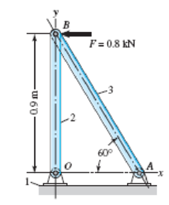
Problem 3–3
Expert Solution & Answer
Want to see the full answer?
Check out a sample textbook solution
Chapter 3 Solutions
Loose Leaf for Shigley's Mechanical Engineering Design Format: LooseLeaf
Ch. 3 - 31 to 34 Sketch a free-body diagram of each...Ch. 3 - 31 to 34 Sketch a free-body diagram of each...Ch. 3 - Sketch a free-body diagram of each element in the...Ch. 3 - 3-1 to 3-4 Sketch a free-body diagram of each...Ch. 3 - 35 to 38 For the beam shown, find the reactions at...Ch. 3 - 35 to 38 For the beam shown, find the reactions at...Ch. 3 - 35 to 38 For the beam shown, find the reactions at...Ch. 3 - For the beam shown, find the reactions at the...Ch. 3 - For the beam shown, find the reactions at the...Ch. 3 - Repeat Prob. 36 using singularity functions...
Ch. 3 - Repeat Prob. 37 using singularity functions...Ch. 3 - Repeat Prob. 38 using singularity functions...Ch. 3 - For a beam from Table A9, as specified by your...Ch. 3 - A beam carrying a uniform load is simply supported...Ch. 3 - For each of the plane stress states listed below,...Ch. 3 - Repeat Prob. 315 for: (a)x = 28 MPa, y = 7 MPa, xy...Ch. 3 - Repeat Prob. 315 for: a) x = 12 kpsi, y = 6 kpsi,...Ch. 3 - For each of the stress states listed below, find...Ch. 3 - Repeat Prob. 318 for: (a)x = 10 kpsi, y = 4 kpsi...Ch. 3 - The state of stress at a point is x = 6, y = 18, z...Ch. 3 - The state of stress at a point is x = 6, y = 18, z...Ch. 3 - Repeat Prob. 320 with x = 10, y = 40, z = 40, xy =...Ch. 3 - A 34-in-diameter steel tension rod is 5 ft long...Ch. 3 - Repeat Prob. 323 except change the rod to aluminum...Ch. 3 - A 30-mm-diameter copper rod is 1 m long with a...Ch. 3 - A diagonal aluminum alloy tension rod of diameter...Ch. 3 - Repeat Prob. 326 with d = 16 mm, l = 3 m, and...Ch. 3 - Repeat Prob. 326 with d = 58 in, l = 10 ft, and...Ch. 3 - Electrical strain gauges were applied to a notched...Ch. 3 - Repeat Prob. 329 for a material of aluminum. 3-29...Ch. 3 - The Roman method for addressing uncertainty in...Ch. 3 - Using our experience with concentrated loading on...Ch. 3 - The Chicago North Shore Milwaukee Railroad was an...Ch. 3 - For each section illustrated, find the second...Ch. 3 - 3-35 to 3-38 For the beam illustrated in the...Ch. 3 - 3-35 to 3-38 For the beam illustrated in the...Ch. 3 - 3-35 to 3-38 For the beam illustrated in the...Ch. 3 - 3-35 to 3-38 For the beam illustrated in the...Ch. 3 - The figure illustrates a number of beam sections....Ch. 3 - A pin in a knuckle joint canning a tensile load F...Ch. 3 - Repeat Prob. 3-40 for a = 6 mm, b = 18 mm. d = 12...Ch. 3 - For the knuckle joint described in Prob. 3-40,...Ch. 3 - The figure illustrates a pin tightly fitted into a...Ch. 3 - For the beam shown, determine (a) the maximum...Ch. 3 - A cantilever beam with a 1-in-diameter round cross...Ch. 3 - Consider a simply supported beam of rectangular...Ch. 3 - In Prob. 346, h 0 as x 0, which cannot occur. If...Ch. 3 - 348 and 349 The beam shown is loaded in the xy and...Ch. 3 - The beam shown is loaded in the xy and xz planes....Ch. 3 - Two steel thin-wall tubes in torsion of equal...Ch. 3 - Consider a 1-in-square steel thin-walled tube...Ch. 3 - The thin-walled open cross-section shown is...Ch. 3 - 3-53 to 3-55 Using the results from Prob. 3-52,...Ch. 3 - 3-53 to 3-55 Using the results from Prob. 3-52,...Ch. 3 - 3-53 to 3-55 Using the results from Prob. 3-52,...Ch. 3 - Two 300-mm-long rectangular steel strips are...Ch. 3 - Using a maximum allowable shear stress of 70 Mpa,...Ch. 3 - Repeat Prob. 357 with an allowable shear stress of...Ch. 3 - Using an allowable shear stress of 50 MPa,...Ch. 3 - A 20-mm-diameter steel bar is to be used as a...Ch. 3 - A 2-ft-long steel bar with a 34-in diameter is to...Ch. 3 - A 40-mm-diameter solid steel shaft, used as a...Ch. 3 - Generalize Prob. 3-62 for a solid shaft of...Ch. 3 - A hollow steel shaft is to transmit 4200 N m of...Ch. 3 - The figure shows an endless-bell conveyor drive...Ch. 3 - The conveyer drive roll in the figure for Prob....Ch. 3 - Consider two shafts in torsion, each of the same...Ch. 3 - 3-68 to 3-71 A countershaft two V-belt pulleys is...Ch. 3 - 3-68 to 3-71 A countershaft two V-belt pulleys is...Ch. 3 - 3-68 to 3-71 A countershaft two V-belt pulleys is...Ch. 3 - A countershaft carrying two V-belt pulleys is...Ch. 3 - A gear reduction unit uses the countershaft shown...Ch. 3 - Prob. 73PCh. 3 - Prob. 74PCh. 3 - Prob. 75PCh. 3 - Prob. 76PCh. 3 - Prob. 77PCh. 3 - Prob. 78PCh. 3 - Prob. 79PCh. 3 - The cantilevered bar in the figure is made from a...Ch. 3 - Repeat Prob. 3-80 with Fx = 0, Fy = 175 lbf, and...Ch. 3 - Repeat Prob. 3-80 with Fx = 75 lbf, Fy= 200 lbf,...Ch. 3 - For the handle in Prob. 3-80, one potential...Ch. 3 - The cantilevered bar in the figure is made from a...Ch. 3 - Repeat Prob. 3-84 with Fx = 300 lbf, Fy = 250 lbf,...Ch. 3 - Repeat Prob. 3-84 with Fx = 300 lbf, Fy = 250 lbf,...Ch. 3 - Repeat Prob. 3-84 for a brittle material,...Ch. 3 - Repeat Prob. 3-84 with Fx = 300 lbf, Fy = 250 lbf,...Ch. 3 - Repeat Prob. 3-84 with Fx = 300 lbf, Fy = 250 lbf,...Ch. 3 - The figure shows a simple model of the loading of...Ch. 3 - Develop the formulas for the maximum radial and...Ch. 3 - Repeat Prob. 391 where the cylinder is subject to...Ch. 3 - Develop the equations for the principal stresses...Ch. 3 - 3-94 to 3-96 A pressure cylinder has an outer...Ch. 3 - 3-94 to 3-96 A pressure cylinder has an outer...Ch. 3 - 3-94 to 3-96A pressure cylinder has an outer...Ch. 3 - 3-97 to 3-99 A pressure cylinder has an outer...Ch. 3 - 3-97 to 3-99 A pressure cylinder has an outer...Ch. 3 - 3-97 to 3-99 A pressure cylinder has an outer...Ch. 3 - An AISI 1040 cold-drawn steel tube has an OD = 50...Ch. 3 - Repeat Prob. 3-100 with an OD of 2 in and wall...Ch. 3 - Prob. 102PCh. 3 - Prob. 103PCh. 3 - A thin-walled cylindrical Steel water storage tank...Ch. 3 - Repeat Prob. 3-104 with the tank being pressurized...Ch. 3 - Find the maximum shear stress in a 512-in-diameter...Ch. 3 - The maximum recommended speed for a...Ch. 3 - An abrasive cutoff wheel has a diameter of 5 in,...Ch. 3 - A rotary lawnmower blade rotates at 3500 rev/min....Ch. 3 - 3110 to 3115 The table lists the maximum and...Ch. 3 - Prob. 111PCh. 3 - Prob. 112PCh. 3 - 3110 to 3115 The table lists the maximum and...Ch. 3 - Prob. 114PCh. 3 - Prob. 115PCh. 3 - 3116 to 3119 The table gives data concerning the...Ch. 3 - Prob. 117PCh. 3 - Prob. 118PCh. 3 - 3116 to 3119 The table gives data concerning the...Ch. 3 - A utility hook was formed from a round rod of...Ch. 3 - A utility hook was formed from a round rod of...Ch. 3 - The steel eyebolt shown in the figure is loaded...Ch. 3 - For Prob. 3122 estimate the stresses at the inner...Ch. 3 - Repeat Prob. 3122 with d = 14 in, Ri = 12 in, and...Ch. 3 - Repeat Prob. 3123 with d = 14 in, Ri = 12 in, and...Ch. 3 - Shown in the figure is a 12-gauge (0.1094-in) by...Ch. 3 - Repeat Prob. 3126 with a 10-gauge (0.1406-in)...Ch. 3 - Prob. 128PCh. 3 - The cast-iron bell-crank lever depicted in the...Ch. 3 - Prob. 130PCh. 3 - Prob. 131PCh. 3 - A cast-steel C frame as shown in the figure has a...Ch. 3 - Two carbon steel balls, each 30 mm in diameter,...Ch. 3 - A carbon steel ball with 25-mm diameter is pressed...Ch. 3 - Repeat Prob. 3134 but determine the maximum shear...Ch. 3 - A carbon steel ball with a 30-mm diameter is...Ch. 3 - An AISI 1018 steel ball with 1-in diameter is used...Ch. 3 - An aluminum alloy cylindrical roller with diameter...Ch. 3 - A pair of mating steel spur gears with a 0.75-in...Ch. 3 - 3140 to 3142 A wheel of diameter d and width w...Ch. 3 - 3140 to 3142 A wheel of diameter d and width w...Ch. 3 - 3140 to 3142 A wheel of diameter d and width w...
Knowledge Booster


Learn more about
Need a deep-dive on the concept behind this application? Look no further. Learn more about this topic, mechanical-engineering and related others by exploring similar questions and additional content below.Similar questions
- Solve the preceding problem if F =90 mm, F = 42 kN, and t = 40°MPaarrow_forwardA large precast concrete panel for a warehouse is raised using two sets of cables at two lift lines, as shown in the figure part a. Cable 1 has a length L1 = 22 Ft, cable 2 has a length L2= 10 ft, and the distance along the panel between lift points Band D is d = 14 ft (see figure part b). The total weight of the panel is W = 85 kips. Assuming the cable lift Forces F at each lift line are about equal, use the simplified model of one half of the panel in figure part b to perform your analysis for the lift position shown. Find the required cross-sectional area AC of the cable if its breaking stress is 91 ksi and a factor of safety of 4 with respect to failure is desired.arrow_forwardA mountain bike is moving along a flat path at constant velocity. At some instant, the rider (weight = 670 N) applies pedal and hand forces, as shown in the figure part a. (a) Find reaction forces at the front and rear hubs. (Assume that the bike is pin supported at the rear hub and roller supported at the front hub.) (b) Find internal stress resultants N, V, and M in the inclined seat post (see figure part barrow_forward
- -19 The mechanical assembly shown in the figure consists of an aluminum tube, a rigid end plate, and two steel cables. The slack is removed from the cables by rotating the turnbuckles until the assembly is snug but with no initial stresses. Afterward, the turnbuckles are tightened by 1.5 turns. Calculate the forces in the tube and the cables and determine the shortening of the tube. As= 0.85 in2 for each cable, AA= 4.5 in2, L = 20 in., Es= 29,000 ksi, EA= 10,600 ksi, and p = 1/16 inarrow_forwardRepeat Problem 11.3-9. Use two C 150 × 12.2 steel shapes and assume that E = 205 GPa and L = 6 m.arrow_forwardA steel punch consists of two shafts: upper shaft and lower shaft. Assume that the upper shaft has a diameter d1= 24 mm and the bottom shaft has a diameter d2= 16 mm. The punch is used to insert a hole in a 4 mm plate, as shown in the figure. If a force P - 70 kN is required to create the hole, what is the average shear stress in the plate and the average compressive stress in the upper and lower shaft of the punch?arrow_forward
- Repeat Problem 2.3-29 if vertical load P at D is replaced by a horizontal load P at D (see figure).arrow_forwardRepeat Problem 6.2-1 but now assume that the steel plate is smaller (0.5 in. × 5 in.) and is aligned with the top of the beam as shown in the figure.arrow_forwardRepeat Problem 9,5-15 for the anti-symmetric loading shown in the figure.arrow_forward
- The propeller shaft of a large ship has an outside diameter 18 in. and inside diameter 12 in,, as shown in the figure. The shaft is rated for a maximum shear stress of 4500 psi. If the shaft is turning at 100 rpm, what is the maximum horsepower that can be transmitted without exceeding the allowable stress? If the rotational speed of the shaft is doubled but the power requirements remain unchanged, what happens to the shear stress in the shaft?arrow_forwardA woodpile, driven into the earth, supports a load P entirely by friction along its sides (see figure part a). The friction force/per unit length of the pile is assumed to be uniformly distributed over the surface of the pile. The pile has a length L, cross-sectional area A. and modulus of elasticity E. (a) Derive a formula for the shorteningarrow_forwardA sign of weight W is supported at its base by four bolls anchored in a concrete footing. Wind pressure P acts normal to the surface of the sign; the resultant of the uniform wind pressure is force fat the center of pressure (C.P). The wind force is assumed to create equal shear forces F/4 in the y direction at each boll (see figure parts a and c). The overturning effect of the wind force also causes an uplift force R at bolts A and C and a downward force (— R) al bolts B and D (see figure part b). The resulting effects of the wind and the associated ultimate stresses for each stress condition are normal stress in each boll (h — 60 ksi); shear through the base plate (th = 17 ksi); horizontal shear and bearing on each bolt ( tfur = 25 ksi and cr^ = 75 ksi): and bearing on the bottom washer at B (or D) (abor = 50 ksi).arrow_forward
arrow_back_ios
SEE MORE QUESTIONS
arrow_forward_ios
Recommended textbooks for you
 Mechanics of Materials (MindTap Course List)Mechanical EngineeringISBN:9781337093347Author:Barry J. Goodno, James M. GerePublisher:Cengage Learning
Mechanics of Materials (MindTap Course List)
Mechanical Engineering
ISBN:9781337093347
Author:Barry J. Goodno, James M. Gere
Publisher:Cengage Learning
Understanding Torsion; Author: The Efficient Engineer;https://www.youtube.com/watch?v=1YTKedLQOa0;License: Standard YouTube License, CC-BY