
Videos
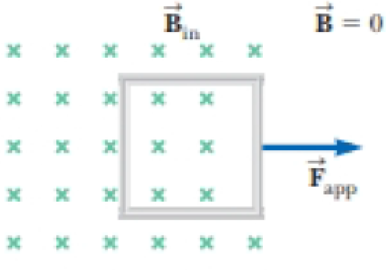
An N-turn square coil with side ℓ and resistance R is pulled to the right at constant speed v in the presence of a uniform magnetic field B acting perpendicular to the coil as shown in Figure P30.43. At t = 0, the right side of the coil has just departed the right edge of the field. At time t, the left side of the coil enters the region where B = 0. In terms of the quantities N, B, ℓ, v, and R, find symbolic expressions for (a) the magnitude of the induced emf in the loop during the time interval from t = 0 to t, (b) the magnitude of the induced current in the coil, (c) the power delivered to the coil, and (d) the force required to remove the coil from the field. (e) What is the direction of the induced current in the loop? (f) What is the direction of the magnetic force on the loop while it is being pulled out of the field?
Figure P30.43

Trending nowThis is a popular solution!

Chapter 30 Solutions
Physics for Scientists and Engineers with Modern Physics
Additional Science Textbook Solutions
Physics for Scientists and Engineers with Modern Physics
Physical Science
Loose Leaf For Explorations: Introduction To Astronomy
University Physics (14th Edition)
Tutorials in Introductory Physics


- A circular coil 15.0 cm in radius and composed of 145 tightly wound turns carries a current of 2.50 A in the counterclockwise direction, where the plane of the coil makes an angle of 15.0 with the y axis (Fig. P30.73). The coil is free to rotate about the z axis and is placed in a region with a uniform magnetic field given by B=1.35jT. a. What is the magnitude of the magnetic torque on the coil? b. In what direction will the coil rotate? FIGURE P30.73arrow_forwardIn Figure P30.38, the rolling axle, 1.50 m long, is pushed along horizontal rails at a constant speed v = 3.00 m/s. A resistor R = 0.400 is connected to the rails at points a and b, directly opposite each other. The wheels make good electrical contact with the rails, so the axle, rails, and R form a closed-loop circuit. The only significant resistance in the circuit is R. A uniform magnetic field B = 0.080 0 T is vertically downward. (a) Find the induced current I in the resistor. (b) What horizontal force F is required to keep the axle rolling at constant speed? (c) Which end of the resistor, a or b, is at the higher electric potential? (d) What If? After the axle rolls past the resistor, does the current in R reverse direction? Explain your answer. Figure P30.38arrow_forwardA long solenoid, with its axis along the x axis, consists of 200 turns per meter of wire that carries a steady current of 15.0 A. A coil is formed by wrapping 30 turns of thin wire around a circular frame that has a radius of 8.00 cm. The coil is placed inside the solenoid and mounted on an axis that is a diameter of the coil and coincides with the y axis. The coil is then rotated with an angular speed of 4.00 rad/s. The plane of the coil is in the yz plane at t = 0. Determine the emf generated in the coil as a function of time.arrow_forward
- A wire is bent in the form of a square loop with sides of length L (Fig. P30.24). If a steady current I flows in the loop, determine the magnitude of the magnetic field at point P in the center of the square. FIGURE P30.24arrow_forwardReview. The bar of mass m in Figure P30.51 is pulled horizontally across parallel, frictionless rails by a massless string that passes over a light, frictionless pulley and is attached to a suspended object of mass M. The uniform upward magnetic field has a magnitude B, and the distance between the rails is . The only significant electrical resistance is the load resistor R shown connecting the rails at one end. Assuming the suspended object is released with the bar at rest at t = 0, derive an expression that gives the bars horizontal speed as a function of time. Figure P30.51arrow_forwardAn N-turn square coil with side and resistance R is pulled to the right at constant speed v in the presence of a uniform magnetic field B acting perpendicular to the coil as shown in Figure P30.43. At t = 0, the right side of the coil has just departed the right edge of the field. At time t, the left side of the coil enters the region where B = 0. In terms of the quantities N, B, , v, and R, find symbolic expressions for (a) the magnitude of the induced emf in the loop during the time interval from t = 0 to t, (b) the magnitude of the induced current in the coil, (c) the power delivered to the coil, and (d) the force required to remove the coil from the field. (e) What is the direction of the induced current in the loop? (f) What is the direction of the magnetic force on the loop while it is being pulled out of the field? Figure P30.43arrow_forward
- A long, straight wire carries a current given by I = Imax sin (t + ). The wire lies in the plane of a rectangular coil of N turns of wire as shown in Figure P30.45. The quantities Imax, , and are all constants. Assume Imax = 50.0 A, = 200 s1, N = 100, h = = 5.00 cm, and L = 20.0 cm. Determine the emf induced in the coil by the magnetic field created by the current in the straight wire. Figure P30.45arrow_forwardA loop of wire in the shape of a rectangle of width w and length L and a long, straight wire carrying a current I lie on a tabletop as shown in Figure P23.7. (a) Determine the magnetic flux through the loop due to the current I. (b) Suppose the current is changing with time according to I = a + bt, where a and b are constants. Determine the emf that is induced in the loop if b = 10.0 A/s, h = 1.00 cm, w = 10.0 cm, and L = 1.00 m. (c) What is the direction of the induced current in the rectangle? Figure P23.7arrow_forwardA Figure P32.74 shows an N-turn rectangular coil of length a and width b entering a region of uniform magnetic field of magnitude Bout directed out of the page. The velocity of the coil is constant and is upward in the figure. The total resistance of the coil is R. What are the magnitude and direction of the magnetic force on the coil a. when only a portion of the coil has entered the region with the field, b. when the coil is completely embedded in the field, and c. as the coil begins to exit the region with the field?arrow_forward
- Three long, current-carrying wires are parallel to one another and separated by a distance d. The magnitudes and directions of the currents are shown in Figure P30.91. Wires 1 and 3 are fixed, but wire 2 is free to move. Wire 2 is displaced to the right by a small distance x. Determine the net force (per unit length) acting on wire 2 and the angular frequency of the resulting oscillation. Assume the mass per unit length of wire 2 is and x d. FIGURE P30.91arrow_forwardA metal rod of mass m slides without friction along two parallel horizontal rails, separated by a distance l and connected by a resistor R, as shown in Figure P23.15. A uniform vertical magnetic field of magnitude B is applied perpendicular to the plane of the paper. The applied force shown in the figure acts only for a moment, to give die rod a speed v. In terms of m, l, R, B, and v, find the distance the rod will then slide as it coasts to a stop.arrow_forwardFigure P30.39 shows a stationary conductor whose shape is similar to the letter e. The radius of its circular portion is a = 50.0 cm. It is placed in a constant magnetic field of 0.500 T directed out of the page. A straight conducting rod, 50.0 cm long, is pivoted about point O and rotates with a constant angular speed of 2.00 rad/s. (a) Determine the induced emf in the loop POQ. Note that the area of the loop is a2/2. (b) If all the conducting material has a resistance per length of 5.00 /m, what is the induced current in the loop POQ at the instant 0.250 s after point P passes point Q? Figure P30.39arrow_forward
 Physics for Scientists and EngineersPhysicsISBN:9781337553278Author:Raymond A. Serway, John W. JewettPublisher:Cengage Learning
 Physics for Scientists and Engineers with Modern ...PhysicsISBN:9781337553292Author:Raymond A. Serway, John W. JewettPublisher:Cengage Learning
 Physics for Scientists and Engineers: Foundations...PhysicsISBN:9781133939146Author:Katz, Debora M.Publisher:Cengage Learning
 Principles of Physics: A Calculus-Based TextPhysicsISBN:9781133104261Author:Raymond A. Serway, John W. JewettPublisher:Cengage Learning
 Physics for Scientists and Engineers, Technology ...PhysicsISBN:9781305116399Author:Raymond A. Serway, John W. JewettPublisher:Cengage Learning