
MECHANICS OF MATERIALS
7th Edition
ISBN: 9781260471076
Author: BEER
Publisher: MCG
expand_more
expand_more
format_list_bulleted
Concept explainers
Videos
Textbook Question
Chapter 3.1, Problem 24P
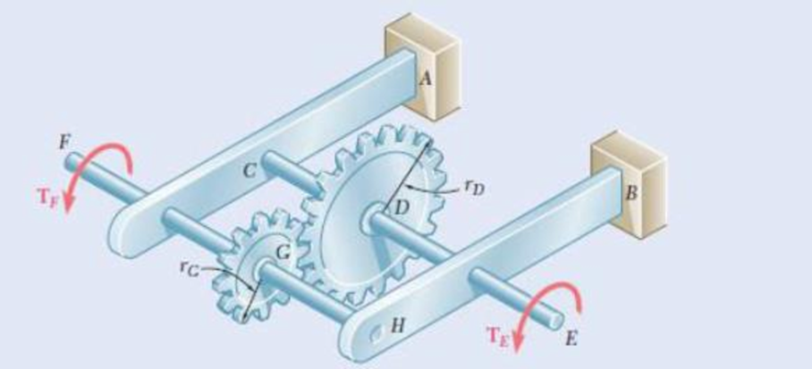
Fig P3.23 and P3.24
3.24 Under normal operating conditions a motor exerts a torque of magnitude TF = 1200 lb in. at F. Knowing that rD= 8 in., rG = 3 in., and the allowable shearing stress is 10.5 ksi in each shaft, determine the required diameter of (a) shaft CDE, (b) shaft FGH.
Expert Solution & Answer
Want to see the full answer?
Check out a sample textbook solution
Students have asked these similar questions
A steel shaft must transmit 150 kW at a speed of 360 rpm. Knowing that G = 77.2 GPa, design a solid shaft so that the maximum shearing stress will not exceed 50 MPa and the angle of twist in a 2.8-m length must not exceed 3°. Consider the frequency f to be 6 Hz. The diameter of the solid shaft is -- mm
The stepped shaft shown rotates at 480 rpm. Knowing that r = 0.2 in. and using figure 3.28, determine the largest torque T that can be transmitted without exceeding an allowable shearing stress of 7000 psi.
The preliminary design of a motor-to-generator connection calls for the use of a large hollow shaft with inner and outer diameters of 4 in. and 6 in., respectively. Knowing that the allowable shearing stress is 12 ksi, determine the maximum torque that can be transmitted by (a) the shaft as designed, (b) a solid shaft of the same weight, and (c) a hollow shaft of the same weight and an 8-in. outer diameter.
Chapter 3 Solutions
MECHANICS OF MATERIALS
Ch. 3.1 - Determine the torque T that causes a maximum...Ch. 3.1 - For the cylindrical shaft shown, determine the...Ch. 3.1 - (a) Determine the torque T that causes a maximum...Ch. 3.1 - (a) Determine the maximum shearing stress caused...Ch. 3.1 - (a) For the 3-in.-diameter solid cylinder and...Ch. 3.1 - Fig. P3.6 3.6 A torque T=3 kN m is applied to the...Ch. 3.1 - The solid spindle AB is made of a steel with an...Ch. 3.1 - The solid spindle AB has a diameter ds = 1.5 in....Ch. 3.1 - Fig. P3.9 and P3.10 3.10 The shafts of the pulley...Ch. 3.1 - Knowing that each of the shafts AB, BC, and CD...
Ch. 3.1 - Fig. P3.11 and P3.12 3.12 Knowing that an...Ch. 3.1 - Under normal operating conditions, the electric...Ch. 3.1 - In order to reduce the total mass of the assembly...Ch. 3.1 - The allowable shearing stress is 15 ksi in the...Ch. 3.1 - The allowable shearing stress is 15 ksi in the...Ch. 3.1 - The solid shaft shown is formed of a brass for...Ch. 3.1 - Solve Prob. 3.17 assuming that the direction of Tc...Ch. 3.1 - The solid rod AB has a diameter dAB= 60 mm and is...Ch. 3.1 - Fig. P3.19 and P3.20 3.20 The solid rod AB has a...Ch. 3.1 - A torque of magnitude T = 1000 N m is applied at D...Ch. 3.1 - Fig. P3.21 and P3.22 3.22 A torque of magnitude T...Ch. 3.1 - Under normal operating conditions a motor exerts a...Ch. 3.1 - Fig P3.23 and P3.24 3.24 Under normal operating...Ch. 3.1 - Prob. 25PCh. 3.1 - Fig. P3.25 and P3.26 3.26 The two solid shafts are...Ch. 3.1 - For the gear train shown, the diameters of the...Ch. 3.1 - Fig. P3.27 and P3.28 3.28 A torque T = 900 N m is...Ch. 3.1 - Fig. P3.29 3.29 While the exact distribution of...Ch. 3.1 - Fig. P3.30 3.30 (a) For a given allowable shearing...Ch. 3.3 - Determine the largest allowable diameter of a...Ch. 3.3 - The ship at A has just started to drill for oil on...Ch. 3.3 - (a) For the solid steel shaft shown, determine the...Ch. 3.3 - (a) For the aluminum pipe shown (G = 27 GPa),...Ch. 3.3 - The electric motor exerts a 500 N m-torque on the...Ch. 3.3 - The torques shown are exerted on pulleys and B....Ch. 3.3 - The aluminum rod BC (G = 26 GPa) is bonded to the...Ch. 3.3 - The aluminum rod AB (G = 27 GPa) is bonded to the...Ch. 3.3 - The solid spindle AB has a diameter ds = 1.75 in....Ch. 3.3 - Fig. p3.39 and p3.40 3.40 The solid spindle AB has...Ch. 3.3 - Two shafts, each of 78in. diameter, are connected...Ch. 3.3 - Two solid steel shafts each of 30-mm diameter, are...Ch. 3.3 - A coder F, used to record in digital form the...Ch. 3.3 - Fig. p3.43 3.44 For the gear train described in...Ch. 3.3 - The design specifications of a 1.2-m-long solid...Ch. 3.3 - 3.46 and 3.47 The solid cylindrical rod BC of...Ch. 3.3 - 3.46 and 3.47 The solid cylindrical rod BC of...Ch. 3.3 - The design of the gear-and-shaft system shown...Ch. 3.3 - The electric motor exerts a torque of 900 Nm on...Ch. 3.3 - A hole is punched at A in a plastic sheet by...Ch. 3.3 - The solid cylinders AB and BC are bonded together...Ch. 3.3 - Solve Prob. 3.51, assuming that cylinder AB is...Ch. 3.3 - The composite shaft shown consists of a...Ch. 3.3 - Fig. p3.53 and p3.54 3.54 The composite shaft...Ch. 3.3 - Two solid steel shafts (G = 77.2 GPa) are...Ch. 3.3 - Solve Prob. 3.55, assuming that the shaft AB is...Ch. 3.3 - 3.57 and 3.58 Two solid steel shafts are fitted...Ch. 3.3 - 3.57 and 3.58 Two solid steel shafts are fitted...Ch. 3.3 - The steel jacket CD has been attached to the...Ch. 3.3 - A torque T is applied as shown to a solid tapered...Ch. 3.3 - Prob. 61PCh. 3.3 - A solid shaft and a hollow shaft are made of the...Ch. 3.3 - An annular plate of thickness t and modulus G is...Ch. 3.5 - Determine the maximum shearing stress in a solid...Ch. 3.5 - Determine the maximum shearing stress in a solid...Ch. 3.5 - Using an allowable shearing stress of 4.5 ksi,...Ch. 3.5 - Using an allowable shearing stress of 50 MPa,...Ch. 3.5 - While a steel shaft of the cross section shown...Ch. 3.5 - Determine the required thickness of the 50-mm...Ch. 3.5 - A steel drive shaft is 6 ft long and its outer and...Ch. 3.5 - The hollow steel shaft shown (G = 77.2 GPa, all =...Ch. 3.5 - A steel pipe of 3.5-in. outer diameter is to be...Ch. 3.5 - 3.73 The design of a machine element calls for a...Ch. 3.5 - Three shafts and four gears are used to form a...Ch. 3.5 - Three shafts and four gears are used to form a...Ch. 3.5 - The two solid shafts and gears shown are used to...Ch. 3.5 - Fig. P3.76 and P3.77 3.77 The two solid shafts and...Ch. 3.5 - The shaft-disk-belt arrangement shown is used to...Ch. 3.5 - A 5-ft-long solid steel shaft of 0.875-in....Ch. 3.5 - A 2.5-m-long steel shaft of 30-mm diameter rotates...Ch. 3.5 - The design specifications of a 1.2-m-long solid...Ch. 3.5 - A 1.5-m-long tubular steel shaft (G = 77.2 GPa) of...Ch. 3.5 - Fig. P3.82 and P3.83 3.83 A 1.5-m-long tubular...Ch. 3.5 - The stepped shaft shown must transmit 40 kW at a...Ch. 3.5 - The stepped shaft shown rotates at 450 rpm....Ch. 3.5 - Knowing that the stepped shaft shown transmits a...Ch. 3.5 - The stepped shaft shown must rotate at a frequency...Ch. 3.5 - Fig. P3.87 and P3.88 3.88 The stepped shaft shown...Ch. 3.5 - A torque of magnitude T = 200 lbin. is applied to...Ch. 3.5 - Fig. P3.89, P3.90 and P3.91 3.90 In the stepped...Ch. 3.5 - In the stepped shaft shown, which has a full...Ch. 3.8 - The solid circular shaft shown is made of a steel...Ch. 3.8 - Prob. 93PCh. 3.8 - Prob. 94PCh. 3.8 - Prob. 95PCh. 3.8 - Fig. P3.95 and P3.96 3.96 The solid shaft shown is...Ch. 3.8 - It is observed that a straightened paper clip can...Ch. 3.8 - The solid shaft shown is made of a mild steel that...Ch. 3.8 - Prob. 99PCh. 3.8 - Prob. 100PCh. 3.8 - Prob. 101PCh. 3.8 - Prob. 102PCh. 3.8 - Prob. 103PCh. 3.8 - Prob. 104PCh. 3.8 - A solid circular rod is made of a material that is...Ch. 3.8 - Prob. 106PCh. 3.8 - Prob. 107PCh. 3.8 - Prob. 108PCh. 3.8 - Prob. 109PCh. 3.8 - Prob. 110PCh. 3.8 - Prob. 111PCh. 3.8 - A 50-mm diameter cylinder is made of a brass for...Ch. 3.8 - Prob. 113PCh. 3.8 - The solid circular drill rod AB is made of a steel...Ch. 3.8 - Prob. 115PCh. 3.8 - Prob. 116PCh. 3.8 - After the solid shaft of Prob. 3.116 has been...Ch. 3.8 - The hollow shaft shown is made of a steel that is...Ch. 3.8 - Prob. 119PCh. 3.8 - Prob. 120PCh. 3.10 - Determine the smallest allowable square cross...Ch. 3.10 - Prob. 122PCh. 3.10 - Using all = 70 MPa and G = 27 GPa, determine for...Ch. 3.10 - Prob. 124PCh. 3.10 - Determine the largest torque T that can be applied...Ch. 3.10 - Each of the two brass bars shown is subjected to a...Ch. 3.10 - Prob. 127PCh. 3.10 - Prob. 128PCh. 3.10 - Prob. 129PCh. 3.10 - Shafts A and B are made of the same material and...Ch. 3.10 - Prob. 131PCh. 3.10 - Shafts A and B are made of the same material and...Ch. 3.10 - Prob. 133PCh. 3.10 - Prob. 134PCh. 3.10 - Prob. 135PCh. 3.10 - A 36-kipin. torque is applied to a 10-ft-long...Ch. 3.10 - A 4-m-long steel member has a W310 60 cross...Ch. 3.10 - Prob. 138PCh. 3.10 - A 5-kipft torque is applied to a hollow aluminum...Ch. 3.10 - A torque T = 750 kNm is applied to the hollow...Ch. 3.10 - A 750-Nm torque is applied to a hollow shaft...Ch. 3.10 - 3.142 and 3.143 A hollow member having the cross...Ch. 3.10 - A hollow member having the cross section shown is...Ch. 3.10 - A 90-Nm torque is applied to a hollow shaft having...Ch. 3.10 - 3.145 and 3.146 A hollow member having the cross...Ch. 3.10 - 3.145 and 3.146 A hollow member having the cross...Ch. 3.10 - A cooling tube having the cross section shown is...Ch. 3.10 - A hollow cylindrical shaft was designed to have a...Ch. 3.10 - Equal torques are applied to thin-walled tubes of...Ch. 3.10 - A hollow cylindrical shaft of length L, mean...Ch. 3 - A steel pipe of 12-in. outer diameter is...Ch. 3 - A torque of magnitude T = 120 Nm is applied to...Ch. 3 - Fig. P3.152 3.153 Two solid shafts are connected...Ch. 3 - Prob. 154RPCh. 3 - Prob. 155RPCh. 3 - A torque of magnitude T = 4 kNm is applied at end...Ch. 3 - Ends A and D of the two solid steel shafts AB and...Ch. 3 - As the hollow steel shaft shown rotates at 180...Ch. 3 - Prob. 159RPCh. 3 - Prob. 160RPCh. 3 - Prob. 161RPCh. 3 - The shaft AB is made of a material that is...
Knowledge Booster


Learn more about
Need a deep-dive on the concept behind this application? Look no further. Learn more about this topic, mechanical-engineering and related others by exploring similar questions and additional content below.Similar questions
- A hollow shaft's inner diameter is half of its outer diameter D. Show that the maximum torque that this shaft can carry is 15/16th of the maximum torque that a solid shaft of diameter D made of the same material can carry.arrow_forwardA torque of magnitude T= 100 N·m is applied to shaft AB of the gear train shown. Knowing that the diameters of the three solid shafts are, respectively, dAB= 21 mm, dCD= 30 mm, and dEF= 40 mm, determine the maximum shearing stress in (a) shaft AB, (b) shaft CD, (c) shaft EF.arrow_forwardUnder normal operating conditions, a motor exerts a torque of magnitude TF at F. The shafts are made of a steel for which the allowable shearing stress is 12 ksi and have diameters dCDE = 0.900 in. and dFGH = 0.800 in. Knowing that rD = 6.5 in. and rG = 4.4 in., determine the largest allowable value of TF.arrow_forward
- A torque of magnitude T = 900 N.m is applied at D as shown. Knowing thatthe diameter of shaft AB is 60 mm and that the diameter of shaft CD is 45mm, determine the maximum shearing stress in (a) shaft AB, (b) shaft CD.arrow_forwardA hollow steel drive shaft (G = 11.2 × 10⁶ psi) is 8 ft long and its outer and inner diameters are respectively equal to 2.50 in. and 1.25 in. Know that the shaft transmits 200 hp while rotating at 1570 rpm.Determine the maximum shearing stress (Ksi)arrow_forwardThe design specifications of a 1.2-m-long solid transmission shaft require that the angle of twist of the shaft not exceed 4° when a torque of 750 N·m is applied. Determine the required diameter of the shaft, knowing that the shaft is made of a steel with an allowable shearing stress of 90 MPa and a modulus of rigidity of 77.2 GPa.arrow_forward
- A composite shaft shown, composed of a steel (G = 77 GPa) core inside an aluminum (G = 25 GPa) jacket, carries a torque, T = 10 kN-m. The shaft is designed such that the aluminum jacket will fail first upon the application of the torque. 1) If the allowable shear strength of aluminum is 45 MPa, determine the minimum thickness, t, of the aluminum jacket, that can carry the torque.2) What must be the minimum shear strength of steel such that the aluminum jacket will fail first?3) Determine the maximum angle of twist that can be applied to the shaft.arrow_forward1. A steel shaft is to be manufactured either as a solid circular or as circular tube. The shaft is required to transmit a torque of 1200 Nm without exceeding an allowable shear stress of 40 MPa, nor an allowable rate of twist of 0.75º/m. For G = 78GPa, determine: a. The required diameter do of the solid shaft.b. The required outer diameter d2 of the hollow shaft if the thickness t of the shaft is specified as one-tenth of the outer diameter.c. The ratio of diameters (that is, the ratio d2/do and the ratio of the weights of the hollow and solid shafts.arrow_forwardA propeller shaft in a ship is 400 mm in diameter and 6 m in length. The allowable shearing stress is 60 MPa and the allowable angle of twist is 2°.If G= 65GPa, determine the maximum torque the shaft can transmit.arrow_forward
- The torques shown are exerted on pulleys A and B. Consider TA = 270 N·m and TB = 400 N·m. Knowing that both shafts are solid, determine the maximum shearing stress in shaft BC. The maximum shearing stress in shaft BC is ____ MPa.arrow_forwardA solid 2.9-in.-diameter bronze [ G = 7100 ksi] shaft is 8-ft long. The allowable shear stress in the shaft is 10.2 ksi and the angle of twist must not exceed 0.034 rad. Determine the maximum horsepower P that this shaft can deliver: (a) when rotating at 182 rpm. (b) when rotating at 644 rpm.arrow_forward200 HP is delivered by a solid circular shaft at 1000 rpm rotational speed. If a hollow shaft is used having an inside diameter equal to the diameter of the solid shaft, determine what must be the outside diameter of this shaft if the angular twist of the hollow and solid shaft is to be equal? The allowable maximum shearing stress is 20,000 psi.arrow_forward
arrow_back_ios
SEE MORE QUESTIONS
arrow_forward_ios
Recommended textbooks for you
 Elements Of ElectromagneticsMechanical EngineeringISBN:9780190698614Author:Sadiku, Matthew N. O.Publisher:Oxford University Press
 Mechanics of Materials (10th Edition)Mechanical EngineeringISBN:9780134319650Author:Russell C. HibbelerPublisher:PEARSON
 Thermodynamics: An Engineering ApproachMechanical EngineeringISBN:9781259822674Author:Yunus A. Cengel Dr., Michael A. BolesPublisher:McGraw-Hill Education
 Control Systems EngineeringMechanical EngineeringISBN:9781118170519Author:Norman S. NisePublisher:WILEY
 Mechanics of Materials (MindTap Course List)Mechanical EngineeringISBN:9781337093347Author:Barry J. Goodno, James M. GerePublisher:Cengage Learning
 Engineering Mechanics: StaticsMechanical EngineeringISBN:9781118807330Author:James L. Meriam, L. G. Kraige, J. N. BoltonPublisher:WILEY
Elements Of Electromagnetics
Mechanical Engineering
ISBN:9780190698614
Author:Sadiku, Matthew N. O.
Publisher:Oxford University Press
Mechanics of Materials (10th Edition)
Mechanical Engineering
ISBN:9780134319650
Author:Russell C. Hibbeler
Publisher:PEARSON
Thermodynamics: An Engineering Approach
Mechanical Engineering
ISBN:9781259822674
Author:Yunus A. Cengel Dr., Michael A. Boles
Publisher:McGraw-Hill Education
Control Systems Engineering
Mechanical Engineering
ISBN:9781118170519
Author:Norman S. Nise
Publisher:WILEY
Mechanics of Materials (MindTap Course List)
Mechanical Engineering
ISBN:9781337093347
Author:Barry J. Goodno, James M. Gere
Publisher:Cengage Learning
Engineering Mechanics: Statics
Mechanical Engineering
ISBN:9781118807330
Author:James L. Meriam, L. G. Kraige, J. N. Bolton
Publisher:WILEY
Everything About COMBINED LOADING in 10 Minutes! Mechanics of Materials; Author: Less Boring Lectures;https://www.youtube.com/watch?v=N-PlI900hSg;License: Standard youtube license