
Concept explainers
Videos
A 4-m-long steel member has a W310 × 60 cross section. Knowing that G = 77.2 GPa and that the allowable shearing stress is 40 MPa, determine (a) the largest torque T that can be applied, (b) the corresponding angle of twist. Refer to Appendix C for the dimensions of the cross section and neglect the effect of stress concentrations. (Hint: consider the web and flanges separately and obtain a relation between the torques exerted on the web and a flange, respectively, by expressing that the resulting angles of twist are equal.)
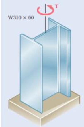
Fig. P3.137
(a)
Find the largest torque (T) that can be applied.
Answer to Problem 137P
The largest torque (T) is
Explanation of Solution
Given information:
The length of the steel member (L) is
The provided section of the member is
The allowable shearing stress
The modulus rigidity of the steel (G) is
Assume the angle of twist in flange and web is equal.
Calculation:
Consider flange:
Refer Appendix C, “Properties of Rolled-Steel shapes”.
The width of the flange (a) is
The thickness of the flange (b) is
Calculate the ratio of width to thickness of the steel
Substitute
Hence, the ratio of
Calculate the ratio of thickness to width of the steel
Substitute
Calculate the coefficient for rectangular bar
Substitute 0.0645 for
Calculate the angle of twist in flange
Here,
Substitute 0.31979 for
Consider web:
Refer Appendix C, “Properties of Rolled-Steel shapes”.
The thickness of the web (b) is
The depth of the member (D) is
Calculate the width of the web (a) using the formula:
Here,
Substitute
Calculate the ratio of width to thickness of the steel
Substitute
Hence, the ratio of
Calculate the ratio of thickness to width of the steel
Substitute
Calculate the coefficient for rectangular bar
Substitute 0.02716 for
Calculate the angle of twist in web
Substitute 0.32763 for
Since the angle of twist in flange and web is equal, therefore,
Substitute
By taking the sum of torque exerted on two flanges and web in the member is equal to the total torque T applied to member. Therefore,
Substitute
Substitute
Calculate the torque in the flange
Substitute
Substitute
Calculate the torque in the web
Substitute
Substitute
Hence, take the lesser value from the torque produced in flange and web respectively.
Therefore, the largest torque (T) is
(b)
Find the angle
Answer to Problem 137P
The angle
Explanation of Solution
Given information:
The length of the steel member (L) is
The provided section of the member is
The allowable shearing stress
The modulus rigidity of the steel (G) is
Assume the angle of twist in flange and web is equal.
Calculation:
From the above calculation of angle of twist, take the critical angle to compute the angle of twist.
Calculate the angle of twist
Substitute
Therefore, the angle of twist of the section is
Want to see more full solutions like this?
Chapter 3 Solutions
Mechanics of Materials, 7th Edition


- The design specifications of a 2-m-long solid circular transmission shaft require that the angle of twist of the shaft not exceed 3° when a torque of 9 kN·m is applied. Determine the required diameter of the shaft, knowing that the shaft is made of (a) a steel with an allowable shearing stress of 90 MPa and a modulus of rigidity of 77 GPa, (b) a bronze with an allowable shearing stress of 35 MPa and a modulus of rigidity of 42 GPaarrow_forwardKnowing that the internal diameter of the hollow shaft shown is d = 0.9 in., determine the maximum shearing stress caused by a torque of magnitude T = 9 kip·in.arrow_forwardUnder normal operating conditions, the electric motor exerts a torque of 2.4 kN·m on shaft AB. Each shaft is solid with diameter d 52 mm. In order to reduce the total mass of the assembly, a new design is being considered in which the diameter of shaft BC will be smaller. Determine the smallest diameter of shaft BC for which the maximum value of the shearing stress in the assembly will not be increased. The smallest diameter of shaft BC is mm.arrow_forward
- The steel jacket CD has been attached to the 40-mm-diameter steel shaft AE by means of rigid flanges welded to the jacket and to the rod. The outer diameter of the jacket is 80 mm and its wall thickness is 4 mm. If 500 N·m torques are applied as shown, determine the maximum shearing stress in the jacket.arrow_forwardA 1.5-m-long tubular steel shaft of 38-mm outer diameter d1 is to be made of a steel for which τall = 65 MPa and G = 77.2 GPa. Knowing that the angle of twist must not exceed 4° when the shaft is subjected to a torque of 660 N·m, determine the largest inner diameter d2 that can be specified in the design. The largest inner diameter d2 that can be specified is mm.arrow_forwardUnder normal operating conditions, a motor exerts a torque of magnitude TF at F. The shafts are made of a steel for which the allowable shearing stress is 12 ksi and have diameters dCDE = 0.900 in. and dFGH = 0.800 in. Knowing that rD = 6.5 in. and rG = 4.4 in., determine the largest allowable value of TF.arrow_forward
- A steel shaft is to be manufactured either as a solid circular or as circular tube. The shaft is required to transmit a torque of 1200 Nm without exceeding an allowable shear stress of 40 MPa, nor an allowable rate of twist of 0.75º/m. For G = 78GPa, determine: The required diameter do of the solid shaft. The required outer diameter d2 of the hollow shaft if the thickness t of the shaft is specified as one-tenth of the outer diameter. The ratio of diameters (that is, the ratio d2/do and the ratio of the weights of the hollow and solid shafts. 1arrow_forwardThe solid spindle AB is made of steel with an allowable shearing stress of 84MPa, and sleeve CD is made of a brass with an allowable shearing stress of50 MPa. Determine (a) the largest torque T that can be applied at A if theallowable shearing stress is not to be exceeded in sleeve CD, (b) thecorresponding required value of the diameter ds of spindle AB.arrow_forwardDetermine the torque capacity of a flange bolt coupling, which consists of nine steel 19-mm diameter bolts spaced evenly around a bolt circle 300 mm in diameter, if the allowable shearing stress in the bolts is 45 MN/m2.arrow_forward
- The solid spindle AB is made of a steel with an allowable shearing stress of 12 ksi, while sleeve CD is made of a brass with an allowable shearing stress of 7 ksi. Determine (a) the largest torque T that can be applied at A if the allowable shearing stress is not to be exceeded in sleeve CD, (b) the corresponding required value of the diameter ds of spindle ABarrow_forwardA 2550-N·m torque T is applied to the hollow shaft as shown. Determine the diameter of a solid shaft for which the maximum shearing stress under the loading shown is the same as in part (a). The diameter of the solid shaft is ____ mm.arrow_forwardThe driveshaft of an automobile is being designed to transmit 238 hp at 3790 rpm. Determine the minimum diameter d required for a solid steel shaft if the allowable shear stress in the shaft is not to exceed 5700 psi.arrow_forward
 Elements Of ElectromagneticsMechanical EngineeringISBN:9780190698614Author:Sadiku, Matthew N. O.Publisher:Oxford University Press
 Mechanics of Materials (10th Edition)Mechanical EngineeringISBN:9780134319650Author:Russell C. HibbelerPublisher:PEARSON
 Thermodynamics: An Engineering ApproachMechanical EngineeringISBN:9781259822674Author:Yunus A. Cengel Dr., Michael A. BolesPublisher:McGraw-Hill Education
 Control Systems EngineeringMechanical EngineeringISBN:9781118170519Author:Norman S. NisePublisher:WILEY
 Mechanics of Materials (MindTap Course List)Mechanical EngineeringISBN:9781337093347Author:Barry J. Goodno, James M. GerePublisher:Cengage Learning
 Engineering Mechanics: StaticsMechanical EngineeringISBN:9781118807330Author:James L. Meriam, L. G. Kraige, J. N. BoltonPublisher:WILEY