
Concept explainers
Videos
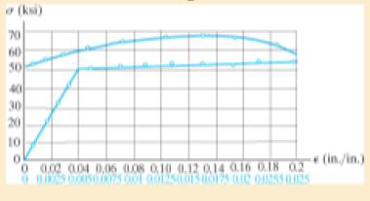
The stress-strain diagram for an aluminum alloy specimen having an original diameter of 0.5 in. and a gage length of 2 in. is given in the figure. Determine approximately the modulus of elasticity for the material, the load on the specimen that causes yielding, and the ultimate load the specimen will support.

Learn your wayIncludes step-by-step video

Chapter 3 Solutions
Modified Mastering Engineering with Pearson eText -- Standalone Access Card -- for Mechanics of Materials
Additional Engineering Textbook Solutions
Thinking Like an Engineer: An Active Learning Approach (3rd Edition)
Applied Fluid Mechanics (7th Edition)
Thinking Like an Engineer: An Active Learning Approach (4th Edition)
Engineering Mechanics: Statics & Dynamics (14th Edition)
Engineering Mechanics: Statics
Engineering Mechanics: Dynamics (14th Edition)


- The rails of a railroad track are welded together at their ends (to form continuous rails and thus eliminate the clacking sound of the wheels) when the temperature is 60°F. What compressive stress ?? =6.5×10⁻⁶ /? is produced in the rails when they are heated by the sun to 120"F if the coefficient of thermal expansion a = the modulus of elasticity E = 30 × 106 psi?arrow_forwardA metal bar AB of a weight Ills suspended by a system of steel wires arranged as shown in the figure. The diameter of the wires is 5/64 in., and the yield stress of the steel is 65 ksi. Determine the maximum permissible weight W max for a factor of safety of 1.9 with respect to yielding.arrow_forwardA wine of length L = 4 ft and diameter d = 0.125 in. is stretched by tensile forces P = 600 lb. The wire is made of a copper alloy having a stress-strain relationship that may be described mathematically by =18,0001+30000.03(=ksi) in which is nondimensional and has units of kips per square inch (ksi). (a) Construct a stress-strain diagram for the material. (bj Determine the elongation, of the wire due to the Forces P. (c) IF the forces are removed, what is the permanent set of the bar? (d) If the forces are applied again, what is the proportional limit?arrow_forward
- A prismatic bar in tension has a length L = 2.0 m and cross-sectional area A =249 mn2. The material of the bar has the stress-strain curve shown in the figure. Determi ne t he elongation 5 of the bar for each of the following axial loads: P = 10 kN, 20 kN, 30 kN, 40 kN. and 45 kN. From these results, plot a diagram of load P versus elongation 5 (load-displacement diagram).arrow_forwardThe strength-to-weight ratio of a structural material is defined as its load-carrying capacity divided by its weight. For materials in tension, use a characteristic tensile stress obtained from a stress-strain curve as a measure of strength. For instance, either the yield stress or the ultimate stress could be used, depending upon the particular application. Thus, the strength-to-weight ratio RS/Wfor a material in tension is defined as Rs/w= in which a is the characteristic stress and 7 is the weight density. Note that the ratio has units of length. Using the ultimate stress Uas the strength parameter, calculate the strength-to-weight ratio (in units of meters) for each of the following materials: aluminum alloy 606I-T6, Douglas fir (in bending}, nylon. structural steel ASTM-A57.2, and a titanium alloy. Obtain the material properties from Tables [-1 and 1-3 of Appendix I. When a range of values is given in a table, use the average value.arrow_forwardAn element of material in plain strain is subjected to strains x = 0.0015, , y . = -0.0002, and xy = 0.0003. (a) Determine the strains for an element oriented at an angle = 20°. (b) Determine the principal strains of the element. Confirm the solution using Mohr’s circle for plane strain.arrow_forward
- A spherical balloon with an outer diameter of 500 mm and thickness 0.3 mm is filled with a gas. Calculate maximum permissible pressure in the balloon if the allowable normal strain at the outer surface of the balloon is O.h Assume E = 4 MPa and v = 0,45.arrow_forwardA spherical balloon is filled with a gas. The outer diameter of the balloon is 20 in. and the thickness is 0,012 in. Calculate the maximum permissible pressure in the balloon if the allowable tensile stress and the allowable shear stress in the balloon are 1 ksi and 0.3 ksi, respectively.arrow_forwardA solid spherical ball of magnesium alloy (E = 6.5 × l0-6 psi, v = 0.35) is lowered into the ocean to a depth of 8000 ft. The diameter of the ball is 9.0 in. (a) Determine the decrease ?d in diameter, the decrease, ?V in volume, and the strain energy U of the ball. (b) At what depth will the volume change be equal to 0.0324% of the original volume?arrow_forward
- A block B is pushed against three springs by a force P (see figure). The middle spring has a stillness K1and the outer springs each have stiffness k^. Initially, the springs are unstressed, and the middle spring is longer than the outer springs (the difference in length is denoted s). (a) Draw a force-displacement diagram with the force P as ordinate and the displacement x of the block as abscissa. (b) From the diagram, determine the strain energy U1 of the springs when x = 2s. (c) Explain why the strain energy E, is not equal to Parrow_forward- 7.2-26 The strains on the surface of an experiment al device made of pure aluminum (E = 70 GPa. v = 0.33) and tested in a space shuttle were measured by means of strain gages. The gages were oriented as shown in the figure. and the measured strains were = 1100 X 106, h = 1496 X 10.6, and = 39.44 X l0_. What is the stress o in the x direction?arrow_forwardA rubber sheet in biaxial stress is subjected to tensile stresses ax= 270 Pa ander,. = 144 Pa. The corresponding strains in the sheet are e. = 0.0002 and = 0.000015. Determine Poisson’s ratio and the modulus elasticity of the material.arrow_forward
 Mechanics of Materials (MindTap Course List)Mechanical EngineeringISBN:9781337093347Author:Barry J. Goodno, James M. GerePublisher:Cengage Learning