
Modified Mastering Engineering with Pearson eText -- Standalone Access Card -- for Mechanics of Materials
10th Edition
ISBN: 9780134321271
Author: Russell C. Hibbeler
Publisher: PEARSON
expand_more
expand_more
format_list_bulleted
Concept explainers
Videos
Textbook Question
Chapter 3.4, Problem 3.6P
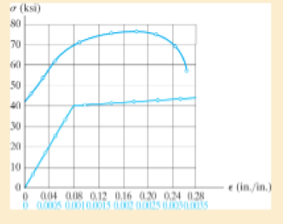
The stress-strain diagram for a steel alloy having an original diameter of 0.5 in. and a gage length of 2 in. is given in the figure. Determine approximately the modulus of resilience and the modulus of toughness for the material.
Prob. 3–6
Expert Solution & Answer
Want to see the full answer?
Check out a sample textbook solution
Students have asked these similar questions
The rod BD is made of material with G1= 124 GPa has a diameter 34 mm is bonded to the tube CA at point B, the tube made of material with G2=211 GPa has an outer diameter 73 mm and wall thickness of 10 mm. If T1=579 N.m and T2=1042 N.m, answer the following questions:
The maximum shear stress of the rod BD is
The maximum shear stress of the tube CA is
The maximum shear stress of the assembly is
The angle of twist between D and B is
The angle of twist between C and A is
The angle of twist at D is
Your answer
The angle of twist between C and B is
Your answer
The reaction at point A is
The bar has a cross-sectional area of 0.5 in2 and is made of a material that has a stress-strain diagram that can be approximated by the two line segments. Determine the elongation of the bar due to the applied loading.
v) A delta strain gauge is attached to the member at point ‘X’ as highlighted in the figure. During a particular stage of a lifting process, strain readings are recorded as detailed. Determine the magnitude and nature of the principal stresses acting on the member at point ‘X’, the maximum shear stress, and the angle of the principal planes.
Young’s Modulus of elasticity = 205 GN/m2Poisson’s ratio = 0.31
Chapter 3 Solutions
Modified Mastering Engineering with Pearson eText -- Standalone Access Card -- for Mechanics of Materials
Ch. 3.4 - Define a homogeneous material.Ch. 3.4 - Indicate the points on the stress-strain diagram...Ch. 3.4 - Define the modulus of elasticity E.Ch. 3.4 - At room temperature, mild steel is a ductile...Ch. 3.4 - Engineering stress and strain are calculated using...Ch. 3.4 - As the temperature increases the modulus of...Ch. 3.4 - A 100-mm-long rod has a diameter of 15 mm. If an...Ch. 3.4 - A bar has a length of 8 in. and cross-sectional...Ch. 3.4 - A 10-mm-diameter rod has a modulus of elasticity...Ch. 3.4 - The material for the 50-mm-long specimen has the...
Ch. 3.4 - The material for the 50-mm-long specimen has the...Ch. 3.4 - If the elongation of wire BC is 0.2 mm after the...Ch. 3.4 - A tension test was performed on a steel specimen...Ch. 3.4 - Data taken from a stress-strain test for a ceramic...Ch. 3.4 - Data taken from a stress-strain test for a ceramic...Ch. 3.4 - The stress-strain diagram for a steel alloy having...Ch. 3.4 - The stress-strain diagram for a steel alloy having...Ch. 3.4 - The stress-strain diagram for a steel alloy having...Ch. 3.4 - The rigid beam is supported by a pin at C and an...Ch. 3.4 - The rigid beam is supported by a pin at C and an...Ch. 3.4 - Acetal plastic has a stress-strain diagram as...Ch. 3.4 - The stress-strain diagram for an aluminum alloy...Ch. 3.4 - The stress-strain diagram for an aluminum alloy...Ch. 3.4 - The stress-strain diagram for an aluminum alloy...Ch. 3.4 - A bar having a length of 5 in. and cross-sectional...Ch. 3.4 - The rigid pipe is supported by a pin at A and an...Ch. 3.4 - The rigid pipe is supported by a pin at A and an...Ch. 3.4 - Direct tension indicators are sometimes used...Ch. 3.4 - The rigid beam is supported by a pin at C and an...Ch. 3.4 - The rigid beam is supported by a pin at C and an...Ch. 3.4 - The stress-strain diagram for a bone is shown, and...Ch. 3.4 - The stress-strain diagram for a bone is shown and...Ch. 3.4 - The two bars are made of a material that has the...Ch. 3.4 - The two bars are made of a material that has the...Ch. 3.4 - The pole is supported by a pin at C and an A-36...Ch. 3.4 - The bar DA is rigid and is originally held in the...Ch. 3.7 - A 100-mm-long rod has a diameter of 15 mm. If an...Ch. 3.7 - A solid circular rod that is 600 mm long and 20 mm...Ch. 3.7 - A 20-mm-wide block is firmly bonded to rigid...Ch. 3.7 - A 20-mm-wide block is bonded to rigid plates at...Ch. 3.7 - The acrylic plastic rod is 200 mm long and 15 mm...Ch. 3.7 - The plug has a diameter of 30 mm and fits within a...Ch. 3.7 - The elastic portion of the stress-strain diagram...Ch. 3.7 - The elastic portion of the stress-strain diagram...Ch. 3.7 - The brake pads for a bicycle tire are made of...Ch. 3.7 - The lap joint is connected together using a 1.25...Ch. 3.7 - The lap joint is connected together using a 1.25...Ch. 3.7 - The rubber block is subjected to an elongation of...Ch. 3.7 - The shear stress-strain diagram for an alloy is...Ch. 3.7 - A shear spring is made from two blocks of rubber,...Ch. 3 - The elastic portion of the tension stress-strain...Ch. 3 - The elastic portion of the tension stress-strain...Ch. 3 - The rigid beam rests in the horizontal position on...Ch. 3 - The wires each have a diameter of 12 in., length...Ch. 3 - The wires each have a diameter of 12 in., length...Ch. 3 - diameter steel bolts. If the clamping force in...Ch. 3 - The stress-strain diagram for polyethylene, which...Ch. 3 - The pipe with two rigid caps attached to its ends...Ch. 3 - The 8-mm-diameter bolt is made of an aluminum...Ch. 3 - An acetal polymer block is fixed to the rigid...
Knowledge Booster


Learn more about
Need a deep-dive on the concept behind this application? Look no further. Learn more about this topic, mechanical-engineering and related others by exploring similar questions and additional content below.Similar questions
- The strain at point A on the bracket has normal components 250x10-6 and 550x10-6 in x and y directions, respectively and shear component -600 x10-6 in x-y plane. Determine the absolute maximum shear strain in 10-6 unit.arrow_forwardThe A-36 steel bar consists of two segments, one of a circular cross-section of radius r, and one of square cross-section. If the bar is subjected to the axial loading of P, determine the dimensions of the square segment so that the strain energy within the square segment is the same as in the circular segment.arrow_forwardAn clement m plane stress from the frame of a racing car is oriented at a known angle 8 (sec figure). On this inclined clement, the normal and shear stresses have the magnitudes and directions shown in the figure. Determine the normal and shear stresses acting on an clement whose sides are parallel to the xy axes, that is, determine crv, tr(_, and t. Show the results on a sketch of an clement oriented at B = 10arrow_forward
- An element of material in plain strain is subjected to shear strain xy = 0.0003. (a) Determine the strains for an element oriented at an angle = 30°. (b) Determine the principal strains of the clement. Confirm the solution using Mohr’s circle for plane strain.arrow_forwardA spherical balloon with an outer diameter of 500 mm and thickness 0.3 mm is filled with a gas. Calculate maximum permissible pressure in the balloon if the allowable normal strain at the outer surface of the balloon is O.h Assume E = 4 MPa and v = 0,45.arrow_forwardA solid spherical ball of magnesium alloy (E = 6.5 × l0-6 psi, v = 0.35) is lowered into the ocean to a depth of 8000 ft. The diameter of the ball is 9.0 in. (a) Determine the decrease ?d in diameter, the decrease, ?V in volume, and the strain energy U of the ball. (b) At what depth will the volume change be equal to 0.0324% of the original volume?arrow_forward
- An element of material in plain strain is subjected to strains x = 0.0015, , y . = -0.0002, and xy = 0.0003. (a) Determine the strains for an element oriented at an angle = 20°. (b) Determine the principal strains of the element. Confirm the solution using Mohr’s circle for plane strain.arrow_forwardThe polysulfone block is glued at its top and bottom to the rigid plates. If a tangential force, applied to the top plate, causes the material to deform so that its sides are described by the equation y = 3.56 x1>4, determine the shear strain at the corners A and B.arrow_forwardA rod has a radius of 10 mm. If it is subjected to an axial load of 15 N such that the axial strain in the rod is P x = 2.75(10-6), determine the modulus of elasticity E and the change in the rod’s diameter. n = 0.23.arrow_forward
- A single strain gage, placed in the vertical plane on the outer surface and at an angle 60° to the axis of the pipe, gives a reading at point A of PA = -250(10-6). Determine the principal strains in the pipe at this point. The pipe has an outer diameter of 1 in. and an inner diameter of 0.6 in. and is made of C86100 bronze.arrow_forwardTwo fully loaded tractor trailers travel over the bridge putting substantial loading on the structure. As they pass over the middle of the bridge, one of the vertical supporting pillars, which is fixed at its bottom, deforms as shown below. The weight of the trucks causes point T to move to point T'—a distance of 2.5 cm along the x-axis. If the pillar has an original height of 27 m , find the shear strain at point T.arrow_forwardThe stress-strain diagram for an aluminum alloy specimen having an original diameter of 0.5 in. and a gauge length of 2 in. is given in the figure. If the specimen is loaded until it is stressed to 60 ksi, determine the approximate amount of elastic recovery and the increase in the gage length after it is unloaded.arrow_forward
arrow_back_ios
SEE MORE QUESTIONS
arrow_forward_ios
Recommended textbooks for you
 Mechanics of Materials (MindTap Course List)Mechanical EngineeringISBN:9781337093347Author:Barry J. Goodno, James M. GerePublisher:Cengage Learning
Mechanics of Materials (MindTap Course List)
Mechanical Engineering
ISBN:9781337093347
Author:Barry J. Goodno, James M. Gere
Publisher:Cengage Learning
Material Properties 101; Author: Real Engineering;https://www.youtube.com/watch?v=BHZALtqAjeM;License: Standard YouTube License, CC-BY