
Modified Mastering Engineering with Pearson eText -- Standalone Access Card -- for Mechanics of Materials
10th Edition
ISBN: 9780134321271
Author: Russell C. Hibbeler
Publisher: PEARSON
expand_more
expand_more
format_list_bulleted
Concept explainers
Videos
Textbook Question
Chapter 3.4, Problem 3.16P
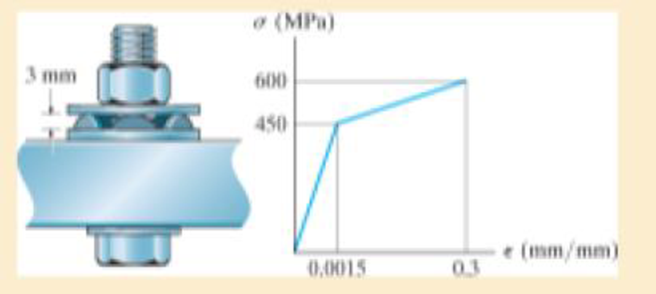
Direct tension indicators are sometimes used instead of torque wrenches to ensure that a bolt has a prescribed tension when used for connections. If a nut on the bolt is tightened so that the six 3-mm high heads of the indicator are strained 0.1 mm/mm, and leave a contact area on each head of 1.5 mm2, determine the tension in the bolt shank. The material has the stress-strain diagram shown.
Prob. 3–16
Expert Solution & Answer
Want to see the full answer?
Check out a sample textbook solution
Students have asked these similar questions
The plastic 50-mm diameter rod is placed in a 51-mm-diameter hole with rigid walls. Determine the change in the length of the rod after the 8 kN load is applied. Use E = 40 MPa and v=0.45 for the rod.
The A-36 steel bar consists of two segments, one of a circular cross-section of radius r, and one of square cross-section. If the bar is subjected to the axial loading of P, determine the dimensions of the square segment so that the strain energy within the square segment is the same as in the circular segment.
The 8-mm-diameter bolt is made of an aluminum alloy. It fits through a magnesium sleeve that has an inner diameter of 12 mm and an outer diameter of 20 mm. If the original lengths of the bolt and sleeve are 80 mm and 50 mm, respectively, determine the strains in the sleeve and the bolt if the nut on the bolt is tightened so that the tension in the bolt is 8 kN. Assume the material at A is rigid. Eal = 70 GPa, Emg = 45 GPa.
Chapter 3 Solutions
Modified Mastering Engineering with Pearson eText -- Standalone Access Card -- for Mechanics of Materials
Ch. 3.4 - Define a homogeneous material.Ch. 3.4 - Indicate the points on the stress-strain diagram...Ch. 3.4 - Define the modulus of elasticity E.Ch. 3.4 - At room temperature, mild steel is a ductile...Ch. 3.4 - Engineering stress and strain are calculated using...Ch. 3.4 - As the temperature increases the modulus of...Ch. 3.4 - A 100-mm-long rod has a diameter of 15 mm. If an...Ch. 3.4 - A bar has a length of 8 in. and cross-sectional...Ch. 3.4 - A 10-mm-diameter rod has a modulus of elasticity...Ch. 3.4 - The material for the 50-mm-long specimen has the...
Ch. 3.4 - The material for the 50-mm-long specimen has the...Ch. 3.4 - If the elongation of wire BC is 0.2 mm after the...Ch. 3.4 - A tension test was performed on a steel specimen...Ch. 3.4 - Data taken from a stress-strain test for a ceramic...Ch. 3.4 - Data taken from a stress-strain test for a ceramic...Ch. 3.4 - The stress-strain diagram for a steel alloy having...Ch. 3.4 - The stress-strain diagram for a steel alloy having...Ch. 3.4 - The stress-strain diagram for a steel alloy having...Ch. 3.4 - The rigid beam is supported by a pin at C and an...Ch. 3.4 - The rigid beam is supported by a pin at C and an...Ch. 3.4 - Acetal plastic has a stress-strain diagram as...Ch. 3.4 - The stress-strain diagram for an aluminum alloy...Ch. 3.4 - The stress-strain diagram for an aluminum alloy...Ch. 3.4 - The stress-strain diagram for an aluminum alloy...Ch. 3.4 - A bar having a length of 5 in. and cross-sectional...Ch. 3.4 - The rigid pipe is supported by a pin at A and an...Ch. 3.4 - The rigid pipe is supported by a pin at A and an...Ch. 3.4 - Direct tension indicators are sometimes used...Ch. 3.4 - The rigid beam is supported by a pin at C and an...Ch. 3.4 - The rigid beam is supported by a pin at C and an...Ch. 3.4 - The stress-strain diagram for a bone is shown, and...Ch. 3.4 - The stress-strain diagram for a bone is shown and...Ch. 3.4 - The two bars are made of a material that has the...Ch. 3.4 - The two bars are made of a material that has the...Ch. 3.4 - The pole is supported by a pin at C and an A-36...Ch. 3.4 - The bar DA is rigid and is originally held in the...Ch. 3.7 - A 100-mm-long rod has a diameter of 15 mm. If an...Ch. 3.7 - A solid circular rod that is 600 mm long and 20 mm...Ch. 3.7 - A 20-mm-wide block is firmly bonded to rigid...Ch. 3.7 - A 20-mm-wide block is bonded to rigid plates at...Ch. 3.7 - The acrylic plastic rod is 200 mm long and 15 mm...Ch. 3.7 - The plug has a diameter of 30 mm and fits within a...Ch. 3.7 - The elastic portion of the stress-strain diagram...Ch. 3.7 - The elastic portion of the stress-strain diagram...Ch. 3.7 - The brake pads for a bicycle tire are made of...Ch. 3.7 - The lap joint is connected together using a 1.25...Ch. 3.7 - The lap joint is connected together using a 1.25...Ch. 3.7 - The rubber block is subjected to an elongation of...Ch. 3.7 - The shear stress-strain diagram for an alloy is...Ch. 3.7 - A shear spring is made from two blocks of rubber,...Ch. 3 - The elastic portion of the tension stress-strain...Ch. 3 - The elastic portion of the tension stress-strain...Ch. 3 - The rigid beam rests in the horizontal position on...Ch. 3 - The wires each have a diameter of 12 in., length...Ch. 3 - The wires each have a diameter of 12 in., length...Ch. 3 - diameter steel bolts. If the clamping force in...Ch. 3 - The stress-strain diagram for polyethylene, which...Ch. 3 - The pipe with two rigid caps attached to its ends...Ch. 3 - The 8-mm-diameter bolt is made of an aluminum...Ch. 3 - An acetal polymer block is fixed to the rigid...
Knowledge Booster


Learn more about
Need a deep-dive on the concept behind this application? Look no further. Learn more about this topic, mechanical-engineering and related others by exploring similar questions and additional content below.Similar questions
- The two bars are made of a material that has the stress-strain diagram shown. If the cross-sectional area of bar AB is 1.5 in2 and BC is 4 in2, determine the largest force P that can be supported before any member fractures. Assume that buckling does not occur.arrow_forwardThe nylon cord has an original length L and is tied to a bolt at A and a roller at B. If a force P is applied to the roller, determine the normal strain in the cord when the roller is at C, and at D. If the cord is originally unstrained when it is at C, determine the normal strain P′ D when the roller moves to D. Show that if the displacements Δ C and Δ D are small, then P′ D = PD − PC.arrow_forwardBefore the load is placed on the rigid plate, the top of the central spring is 20 mm lower than the outer springs. Each outer spring is made of 24 turns of 15-mm diameter wire on a mean radius of 60 mm. The central spring consists of 16 turns of 20 mm dimeter wire on a mean radius of 80 mm. If a load P = 5 kN is now placed on the rigid plate. Disregarding the weight of the plate, use G = 83 GPa and use Light spring formula. Determine the maximum shearing stress of the in uter spring. In MPaarrow_forward
- The three steel wires are used to support the load. If the wires have an allowable tensile stress of σallow = 165 MPa, and wire AB has a diameter of 5 mm, wire BD has a diameter of 7 mm and wire BC has a diameter of 6 mm. Determine the maximum force P that can be applied before one of the wires fails.arrow_forwardThe bar DA is rigid and is originally held in the horizontal position when the weight W is supported from C. If the weight causes B to displace downward 0.025 in., determine the strain in wires DE and BC. Also, if the wires are made of A-36 steel and have a cross-sectional area of 0.002 in2, determine the weight W.arrow_forwardThe coupling rod is subjected to a force of 5 kip. Determine the distance d between C and E accounting for the compression of the spring and the deformation of the bolts. When no load is applied the spring is unstretched and d = 10 in. The material is A-36 steel and each bolt has a diameter of 0.25 in. The plates at A, B, and C are rigid and the spring has a stiffness of k = 12 kip>in.arrow_forward
- The rigid lever arm is supported by two A-36 steel wires having the same diameter of 4 mm. If a force of P = 3 kN is applied to the handle, determine the force developed in both wires and their corresponding elongations. Consider A-36 steel as an elastic perfectly plastic material.arrow_forwardThe hanger is supported using a rectangular pin. Determine the magnitude of the allowable suspended load P if the allowable bearing stress is (σb)allow=220 MPa, the allowable tensile stress is (σt)allow=150 MPa, and the allowable shear stress is τallow=130 MPa. Take t=6 mm, a=5 mm, and b=25 mm. draw free-body diagramarrow_forwardThe 10-mm-diameter bolt is made of an aluminum alloy. It fits through a magnesium sleeve that has an inner diameter of 14 mm and an outer diameter of 22 mm. The original lengths of the bolt and sleeve are 80 mm and 50 mm, respectively. If after the nut on the bolt is tightened the tension in the bolt is 10 kN, determine the change of volume of the bolt and the new length of the sleeve. Wherein both materials behave linearly elastic. Assume the material at A is rigid. E = 70 GPa, Emg = 46 GPa, Ga = 27 GPa, Gmg = 20 GPa.arrow_forward
- The force applied at the handle of the rigid lever causes thelever to rotate clockwise about the pin B through an angleof 2.Determine the average normal strain in each wire. Hint: Thewires are unstretched when the lever is in the horizontalposition.arrow_forwardThe 10-mm-diameter steel bolt is surrounded by a bronze sleeve. The outer diameter of this sleeve is 20 mm, and its inner diameter is 10 mm. If the yield stress for the steel is (sY)st = 640 MPa, and for the bronze (sY)br = 520 MPa,determine the magnitude of the largest elastic load P that can be applied to the assembly. Est = 200 GPa, Ebr = 100 GPa.arrow_forwardThe metal strap has a thickness t and width w and is subjected to a temperature gradient T1 to T2 (T1 6 T2). This causes the modulus of elasticity for the material to vary linearly from E1 at the top to a smaller amount E2 at the bottom. As a result, for any vertical position y, measured from the top surface, E = [(E2 - E1)>w]y + E1. Determine the position d where the axial force P must be applied so that the bar stretches uniformly over its cross-section. warrow_forward
arrow_back_ios
SEE MORE QUESTIONS
arrow_forward_ios
Recommended textbooks for you
 Elements Of ElectromagneticsMechanical EngineeringISBN:9780190698614Author:Sadiku, Matthew N. O.Publisher:Oxford University Press
 Mechanics of Materials (10th Edition)Mechanical EngineeringISBN:9780134319650Author:Russell C. HibbelerPublisher:PEARSON
 Thermodynamics: An Engineering ApproachMechanical EngineeringISBN:9781259822674Author:Yunus A. Cengel Dr., Michael A. BolesPublisher:McGraw-Hill Education
 Control Systems EngineeringMechanical EngineeringISBN:9781118170519Author:Norman S. NisePublisher:WILEY
 Mechanics of Materials (MindTap Course List)Mechanical EngineeringISBN:9781337093347Author:Barry J. Goodno, James M. GerePublisher:Cengage Learning
 Engineering Mechanics: StaticsMechanical EngineeringISBN:9781118807330Author:James L. Meriam, L. G. Kraige, J. N. BoltonPublisher:WILEY
Elements Of Electromagnetics
Mechanical Engineering
ISBN:9780190698614
Author:Sadiku, Matthew N. O.
Publisher:Oxford University Press
Mechanics of Materials (10th Edition)
Mechanical Engineering
ISBN:9780134319650
Author:Russell C. Hibbeler
Publisher:PEARSON
Thermodynamics: An Engineering Approach
Mechanical Engineering
ISBN:9781259822674
Author:Yunus A. Cengel Dr., Michael A. Boles
Publisher:McGraw-Hill Education
Control Systems Engineering
Mechanical Engineering
ISBN:9781118170519
Author:Norman S. Nise
Publisher:WILEY
Mechanics of Materials (MindTap Course List)
Mechanical Engineering
ISBN:9781337093347
Author:Barry J. Goodno, James M. Gere
Publisher:Cengage Learning
Engineering Mechanics: Statics
Mechanical Engineering
ISBN:9781118807330
Author:James L. Meriam, L. G. Kraige, J. N. Bolton
Publisher:WILEY
Hand Tools; Author: UCI Media;https://www.youtube.com/watch?v=4o0tqF0jDdo;License: Standard Youtube License