
Modified Mastering Engineering with Pearson eText -- Standalone Access Card -- for Mechanics of Materials
10th Edition
ISBN: 9780134321271
Author: Russell C. Hibbeler
Publisher: PEARSON
expand_more
expand_more
format_list_bulleted
Concept explainers
Videos
Textbook Question
Chapter 3.4, Problem 3.11P
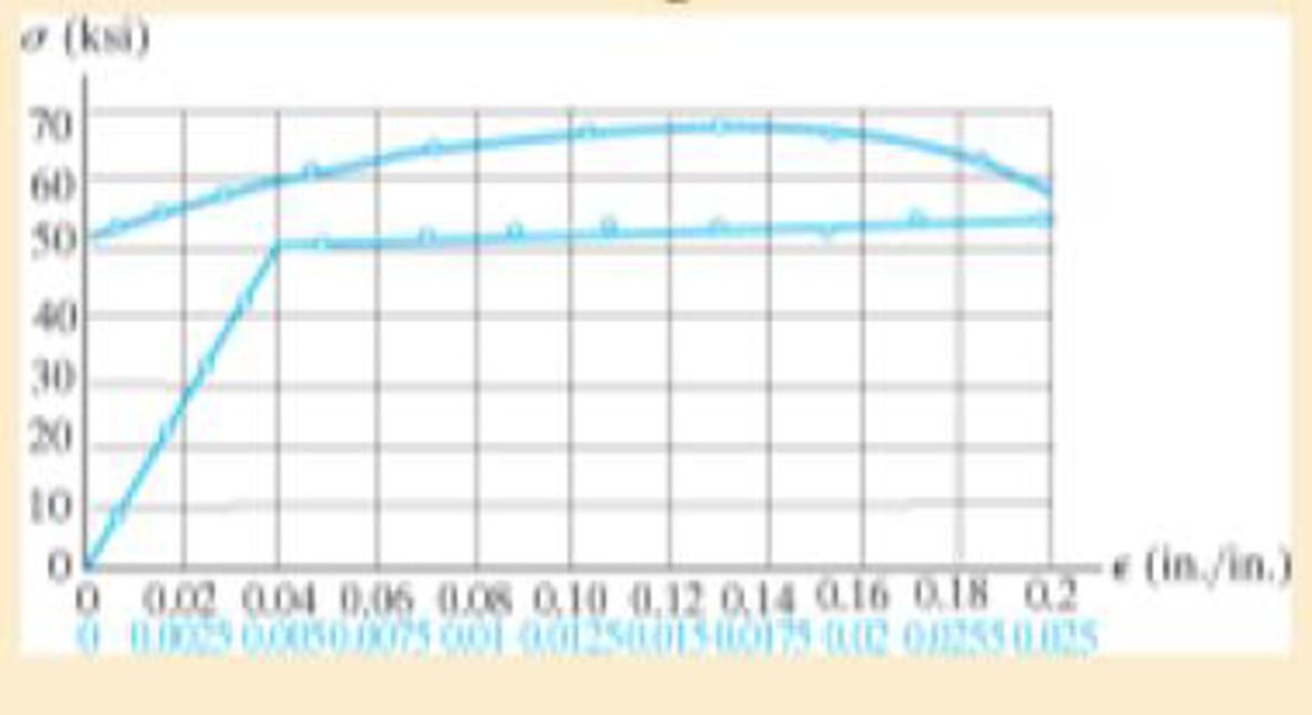
The stress-strain diagram for an aluminum alloy specimen having an original diameter of 0.5 in. and a gage length of 2 in. is given in the figure. If the specimen is loaded until it is stressed to 60 ksi, determine the approximate amount of elastic recovery and the increase in the gage length after it is unloaded.
Expert Solution & Answer

Trending nowThis is a popular solution!

Students have asked these similar questions
The stress-strain diagram for an aluminum alloy specimen having an original diameter of 0.5 in. and a gauge length of 2 in. is given in the figure. If the specimen is loaded until it is stressed to 60 ksi, determine the approximate amount of elastic recovery and the increase in the gage length after it is unloaded.
The stress–strain diagram for a steel alloy having an original diameter of 0.5 in. and a gage length of 2 in. is given in the figure. If the specimen is loaded until it is stressed to 70 ksi, determine the approximate amount of elasticrecovery and the increase in the gage length after it is unloaded.
Chapter 3 Solutions
Modified Mastering Engineering with Pearson eText -- Standalone Access Card -- for Mechanics of Materials
Ch. 3.4 - Define a homogeneous material.Ch. 3.4 - Indicate the points on the stress-strain diagram...Ch. 3.4 - Define the modulus of elasticity E.Ch. 3.4 - At room temperature, mild steel is a ductile...Ch. 3.4 - Engineering stress and strain are calculated using...Ch. 3.4 - As the temperature increases the modulus of...Ch. 3.4 - A 100-mm-long rod has a diameter of 15 mm. If an...Ch. 3.4 - A bar has a length of 8 in. and cross-sectional...Ch. 3.4 - A 10-mm-diameter rod has a modulus of elasticity...Ch. 3.4 - The material for the 50-mm-long specimen has the...
Ch. 3.4 - The material for the 50-mm-long specimen has the...Ch. 3.4 - If the elongation of wire BC is 0.2 mm after the...Ch. 3.4 - A tension test was performed on a steel specimen...Ch. 3.4 - Data taken from a stress-strain test for a ceramic...Ch. 3.4 - Data taken from a stress-strain test for a ceramic...Ch. 3.4 - The stress-strain diagram for a steel alloy having...Ch. 3.4 - The stress-strain diagram for a steel alloy having...Ch. 3.4 - The stress-strain diagram for a steel alloy having...Ch. 3.4 - The rigid beam is supported by a pin at C and an...Ch. 3.4 - The rigid beam is supported by a pin at C and an...Ch. 3.4 - Acetal plastic has a stress-strain diagram as...Ch. 3.4 - The stress-strain diagram for an aluminum alloy...Ch. 3.4 - The stress-strain diagram for an aluminum alloy...Ch. 3.4 - The stress-strain diagram for an aluminum alloy...Ch. 3.4 - A bar having a length of 5 in. and cross-sectional...Ch. 3.4 - The rigid pipe is supported by a pin at A and an...Ch. 3.4 - The rigid pipe is supported by a pin at A and an...Ch. 3.4 - Direct tension indicators are sometimes used...Ch. 3.4 - The rigid beam is supported by a pin at C and an...Ch. 3.4 - The rigid beam is supported by a pin at C and an...Ch. 3.4 - The stress-strain diagram for a bone is shown, and...Ch. 3.4 - The stress-strain diagram for a bone is shown and...Ch. 3.4 - The two bars are made of a material that has the...Ch. 3.4 - The two bars are made of a material that has the...Ch. 3.4 - The pole is supported by a pin at C and an A-36...Ch. 3.4 - The bar DA is rigid and is originally held in the...Ch. 3.7 - A 100-mm-long rod has a diameter of 15 mm. If an...Ch. 3.7 - A solid circular rod that is 600 mm long and 20 mm...Ch. 3.7 - A 20-mm-wide block is firmly bonded to rigid...Ch. 3.7 - A 20-mm-wide block is bonded to rigid plates at...Ch. 3.7 - The acrylic plastic rod is 200 mm long and 15 mm...Ch. 3.7 - The plug has a diameter of 30 mm and fits within a...Ch. 3.7 - The elastic portion of the stress-strain diagram...Ch. 3.7 - The elastic portion of the stress-strain diagram...Ch. 3.7 - The brake pads for a bicycle tire are made of...Ch. 3.7 - The lap joint is connected together using a 1.25...Ch. 3.7 - The lap joint is connected together using a 1.25...Ch. 3.7 - The rubber block is subjected to an elongation of...Ch. 3.7 - The shear stress-strain diagram for an alloy is...Ch. 3.7 - A shear spring is made from two blocks of rubber,...Ch. 3 - The elastic portion of the tension stress-strain...Ch. 3 - The elastic portion of the tension stress-strain...Ch. 3 - The rigid beam rests in the horizontal position on...Ch. 3 - The wires each have a diameter of 12 in., length...Ch. 3 - The wires each have a diameter of 12 in., length...Ch. 3 - diameter steel bolts. If the clamping force in...Ch. 3 - The stress-strain diagram for polyethylene, which...Ch. 3 - The pipe with two rigid caps attached to its ends...Ch. 3 - The 8-mm-diameter bolt is made of an aluminum...Ch. 3 - An acetal polymer block is fixed to the rigid...
Knowledge Booster


Learn more about
Need a deep-dive on the concept behind this application? Look no further. Learn more about this topic, mechanical-engineering and related others by exploring similar questions and additional content below.Similar questions
- The rails of a railroad track are welded together at their ends (to form continuous rails and thus eliminate the clacking sound of the wheels) when the temperature is 60°F. What compressive stress ?? =6.5×10⁻⁶ /? is produced in the rails when they are heated by the sun to 120"F if the coefficient of thermal expansion a = the modulus of elasticity E = 30 × 106 psi?arrow_forwardAn element of material in plain strain is subjected to strains x = 0.0015, , y . = -0.0002, and xy = 0.0003. (a) Determine the strains for an element oriented at an angle = 20°. (b) Determine the principal strains of the element. Confirm the solution using Mohr’s circle for plane strain.arrow_forward- 7.2-26 The strains on the surface of an experiment al device made of pure aluminum (E = 70 GPa. v = 0.33) and tested in a space shuttle were measured by means of strain gages. The gages were oriented as shown in the figure. and the measured strains were = 1100 X 106, h = 1496 X 10.6, and = 39.44 X l0_. What is the stress o in the x direction?arrow_forward
- Solve the preceding problem if the plate is made of aluminum with E = 72 GPa and Poisson’s ratio v = 0.33. The plate is loaded in biaxial stress with normal stress sx= 79 MPa, angle Ø = 18°, and the strain measured by the gage is e = 925 × 10-6.arrow_forwardA joint between two glass plates A and B is filled with a flexible epoxy that bonds securely to the glass. The height of the joint is/p = 0.5 in, its length is L = 30 in, and its thickness is/ = 0.5 in. Shear force of I' = 25 kips is applied to the joint. Calculate the displacement of the joint if the shear modulus of elasticity G of the epoxy is 100 ksi. Calculate the average shear strain in the epoxy.arrow_forwardA metal bar AB of a weight Ills suspended by a system of steel wires arranged as shown in the figure. The diameter of the wires is 5/64 in., and the yield stress of the steel is 65 ksi. Determine the maximum permissible weight W max for a factor of safety of 1.9 with respect to yielding.arrow_forward
- A prismatic bar in tension has a length L = 2.0 m and cross-sectional area A =249 mn2. The material of the bar has the stress-strain curve shown in the figure. Determi ne t he elongation 5 of the bar for each of the following axial loads: P = 10 kN, 20 kN, 30 kN, 40 kN. and 45 kN. From these results, plot a diagram of load P versus elongation 5 (load-displacement diagram).arrow_forwardA block B is pushed against three springs by a force P (see figure). The middle spring has a stillness K1and the outer springs each have stiffness k^. Initially, the springs are unstressed, and the middle spring is longer than the outer springs (the difference in length is denoted s). (a) Draw a force-displacement diagram with the force P as ordinate and the displacement x of the block as abscissa. (b) From the diagram, determine the strain energy U1 of the springs when x = 2s. (c) Explain why the strain energy E, is not equal to Parrow_forwardA wine of length L = 4 ft and diameter d = 0.125 in. is stretched by tensile forces P = 600 lb. The wire is made of a copper alloy having a stress-strain relationship that may be described mathematically by =18,0001+30000.03(=ksi) in which is nondimensional and has units of kips per square inch (ksi). (a) Construct a stress-strain diagram for the material. (bj Determine the elongation, of the wire due to the Forces P. (c) IF the forces are removed, what is the permanent set of the bar? (d) If the forces are applied again, what is the proportional limit?arrow_forward
- A spherical balloon is filled with a gas. The outer diameter of the balloon is 20 in. and the thickness is 0,012 in. Calculate the maximum permissible pressure in the balloon if the allowable tensile stress and the allowable shear stress in the balloon are 1 ksi and 0.3 ksi, respectively.arrow_forwardA rubber sheet in biaxial stress is subjected to tensile stresses ax= 270 Pa ander,. = 144 Pa. The corresponding strains in the sheet are e. = 0.0002 and = 0.000015. Determine Poisson’s ratio and the modulus elasticity of the material.arrow_forwardA two-story building has steel columns AB in the first floor and BC in the second floor, as shown in the figure. The roof load P:equals 400 KN, and the second-floor load P-, equals 720 kN. Each column has a length L = 3.75 m. The cross-sectional areas of the first- and second-floor columns are 11,000 mm" and 3900 mm", respectively. (a) Assuming that E = 206 GPa. determine the total shortenings aof the two columns due to the combined action of the loads Ptand P,. (b) How much additional load P0can be placed at t he top of t he column (point C) if t he total shortening: SACis not to exceed 4.0 mm?arrow_forward
arrow_back_ios
SEE MORE QUESTIONS
arrow_forward_ios
Recommended textbooks for you
 Mechanics of Materials (MindTap Course List)Mechanical EngineeringISBN:9781337093347Author:Barry J. Goodno, James M. GerePublisher:Cengage Learning
Mechanics of Materials (MindTap Course List)
Mechanical Engineering
ISBN:9781337093347
Author:Barry J. Goodno, James M. Gere
Publisher:Cengage Learning
Strain energy and strain energy density introduced; Author: Engineer4Free;https://www.youtube.com/watch?v=m14sqLGg4BQ;License: Standard youtube license