
Modified Mastering Engineering with Pearson eText -- Standalone Access Card -- for Mechanics of Materials
10th Edition
ISBN: 9780134321271
Author: Russell C. Hibbeler
Publisher: PEARSON
expand_more
expand_more
format_list_bulleted
Videos
Textbook Question
Chapter 3.4, Problem 3.4P
The stress-strain diagram for a steel alloy having an original diameter of 0.5 in. and a gage length of 2 in. is given in the figure. Determine approximately the modulus of elasticity for the material, the load on the specimen that causes yielding, and the ultimate load the specimen will support.
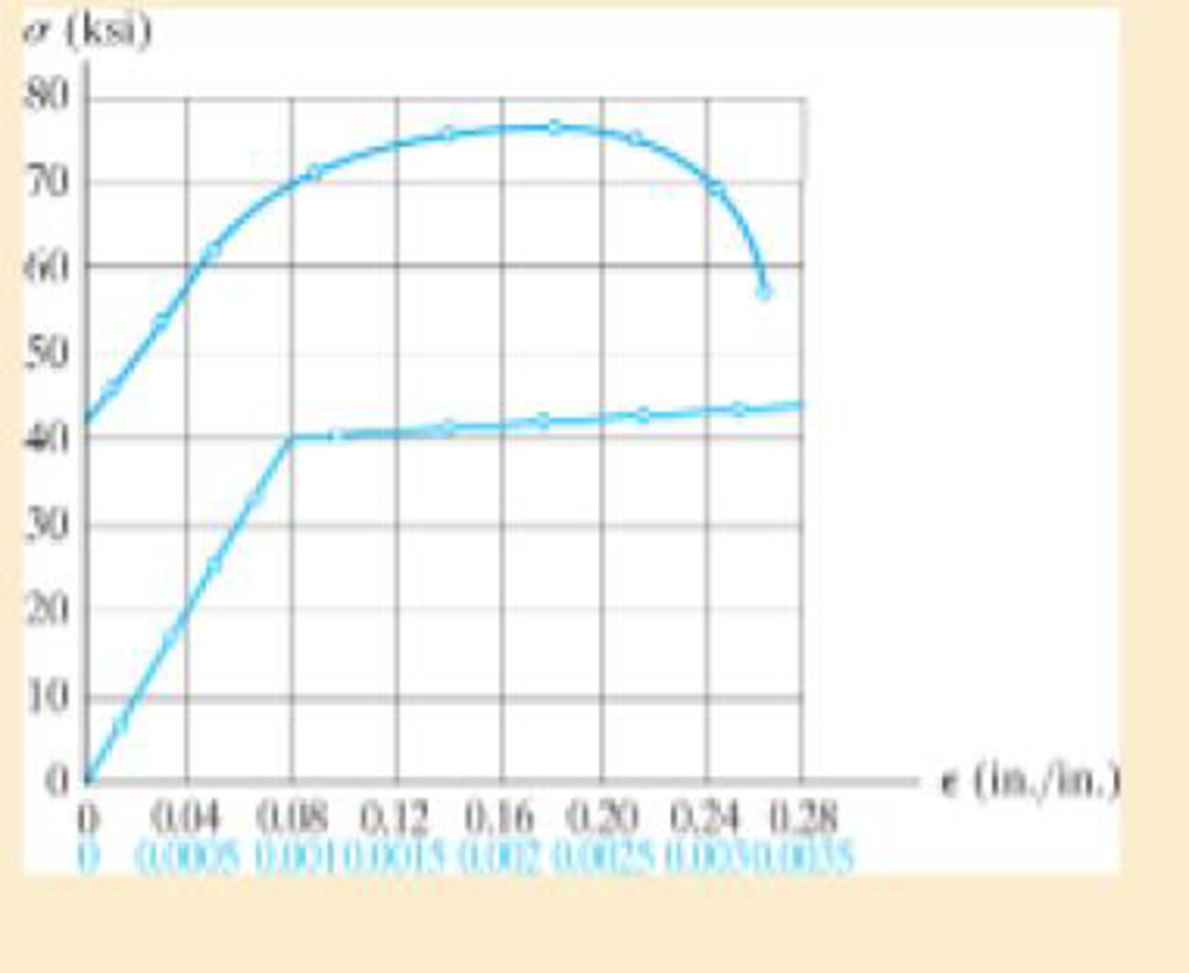
Prob. 3–4
Expert Solution & Answer
Want to see the full answer?
Check out a sample textbook solution
Students have asked these similar questions
The stress-strain diagram for an aluminum alloy specimen having an original diameter of 0.5 in. and a gauge length of 2 in. is given in the figure. If the specimen is loaded until it is stressed to 60 ksi, determine the approximate amount of elastic recovery and the increase in the gage length after it is unloaded.
A short post constructed from a hollow circular tube of aluminum supports a compressive load of 54 kips. The inner and outer diameters of the tube are d1=3.6 in. and d2=5.0 in., respectively, and its length is 40 in. The shortening of the post due to the load is measured as 0.022 in. Determine the compressive stress and strain in the post. (Disregard the weight of the post itself, and assume that the post does not buckle under the load.)
5
The stress-strain diagram for a steel alloy having an original diameter of 0.5 in. and a gauge length of 2 in. is given in the figure. Determine approximately the modulus of elasticity for the material, the load on the specimen that causes yielding, and the ultimate load the specimen will support.
Chapter 3 Solutions
Modified Mastering Engineering with Pearson eText -- Standalone Access Card -- for Mechanics of Materials
Ch. 3.4 - Define a homogeneous material.Ch. 3.4 - Indicate the points on the stress-strain diagram...Ch. 3.4 - Define the modulus of elasticity E.Ch. 3.4 - At room temperature, mild steel is a ductile...Ch. 3.4 - Engineering stress and strain are calculated using...Ch. 3.4 - As the temperature increases the modulus of...Ch. 3.4 - A 100-mm-long rod has a diameter of 15 mm. If an...Ch. 3.4 - A bar has a length of 8 in. and cross-sectional...Ch. 3.4 - A 10-mm-diameter rod has a modulus of elasticity...Ch. 3.4 - The material for the 50-mm-long specimen has the...
Ch. 3.4 - The material for the 50-mm-long specimen has the...Ch. 3.4 - If the elongation of wire BC is 0.2 mm after the...Ch. 3.4 - A tension test was performed on a steel specimen...Ch. 3.4 - Data taken from a stress-strain test for a ceramic...Ch. 3.4 - Data taken from a stress-strain test for a ceramic...Ch. 3.4 - The stress-strain diagram for a steel alloy having...Ch. 3.4 - The stress-strain diagram for a steel alloy having...Ch. 3.4 - The stress-strain diagram for a steel alloy having...Ch. 3.4 - The rigid beam is supported by a pin at C and an...Ch. 3.4 - The rigid beam is supported by a pin at C and an...Ch. 3.4 - Acetal plastic has a stress-strain diagram as...Ch. 3.4 - The stress-strain diagram for an aluminum alloy...Ch. 3.4 - The stress-strain diagram for an aluminum alloy...Ch. 3.4 - The stress-strain diagram for an aluminum alloy...Ch. 3.4 - A bar having a length of 5 in. and cross-sectional...Ch. 3.4 - The rigid pipe is supported by a pin at A and an...Ch. 3.4 - The rigid pipe is supported by a pin at A and an...Ch. 3.4 - Direct tension indicators are sometimes used...Ch. 3.4 - The rigid beam is supported by a pin at C and an...Ch. 3.4 - The rigid beam is supported by a pin at C and an...Ch. 3.4 - The stress-strain diagram for a bone is shown, and...Ch. 3.4 - The stress-strain diagram for a bone is shown and...Ch. 3.4 - The two bars are made of a material that has the...Ch. 3.4 - The two bars are made of a material that has the...Ch. 3.4 - The pole is supported by a pin at C and an A-36...Ch. 3.4 - The bar DA is rigid and is originally held in the...Ch. 3.7 - A 100-mm-long rod has a diameter of 15 mm. If an...Ch. 3.7 - A solid circular rod that is 600 mm long and 20 mm...Ch. 3.7 - A 20-mm-wide block is firmly bonded to rigid...Ch. 3.7 - A 20-mm-wide block is bonded to rigid plates at...Ch. 3.7 - The acrylic plastic rod is 200 mm long and 15 mm...Ch. 3.7 - The plug has a diameter of 30 mm and fits within a...Ch. 3.7 - The elastic portion of the stress-strain diagram...Ch. 3.7 - The elastic portion of the stress-strain diagram...Ch. 3.7 - The brake pads for a bicycle tire are made of...Ch. 3.7 - The lap joint is connected together using a 1.25...Ch. 3.7 - The lap joint is connected together using a 1.25...Ch. 3.7 - The rubber block is subjected to an elongation of...Ch. 3.7 - The shear stress-strain diagram for an alloy is...Ch. 3.7 - A shear spring is made from two blocks of rubber,...Ch. 3 - The elastic portion of the tension stress-strain...Ch. 3 - The elastic portion of the tension stress-strain...Ch. 3 - The rigid beam rests in the horizontal position on...Ch. 3 - The wires each have a diameter of 12 in., length...Ch. 3 - The wires each have a diameter of 12 in., length...Ch. 3 - diameter steel bolts. If the clamping force in...Ch. 3 - The stress-strain diagram for polyethylene, which...Ch. 3 - The pipe with two rigid caps attached to its ends...Ch. 3 - The 8-mm-diameter bolt is made of an aluminum...Ch. 3 - An acetal polymer block is fixed to the rigid...
Knowledge Booster


Learn more about
Need a deep-dive on the concept behind this application? Look no further. Learn more about this topic, mechanical-engineering and related others by exploring similar questions and additional content below.Similar questions
- A spherical balloon with an outer diameter of 500 mm and thickness 0.3 mm is filled with a gas. Calculate maximum permissible pressure in the balloon if the allowable normal strain at the outer surface of the balloon is O.h Assume E = 4 MPa and v = 0,45.arrow_forwardThe shear stress–strain diagram for an alloy is shown in the figure. If a bolt having a diameter of 0.25 in. is made of this material and used in the lap joint, determine the modulus of elasticity E and the force P required to cause the material to yield. Take n = 0.3.arrow_forwardThe elastic portion of the stress–strain diagram for an aluminum alloy is shown in the figure. The specimen from which it was obtained has an original diameter of 12.7 mm and a gage length of 50.8 mm. If a load of P = 60 kN is applied to the specimen, determine its new diameter and length. Taken = 0.35.arrow_forward
- The wire BC has a diameter of 3.4 mm and the material has the stress-strain characteristics shown in the figure. Determine the vertical displacement of the handle at D if the pull at the grip is slowly increased and reaches a magnitude of (a) P = 2250 N, (b) P = 3000 N.arrow_forwardThe stress–strain diagram for a steel alloy having an original diameter of 0.5 in. and a gage length of 2 in. is given in the figure. If the specimen is loaded until it is stressed to 70 ksi, determine the approximate amount of elasticrecovery and the increase in the gage length after it is unloaded.arrow_forwardv) A delta strain gauge is attached to the member at point ‘X’ as highlighted in the figure. During a particular stage of a lifting process, strain readings are recorded as detailed. Determine the magnitude and nature of the principal stresses acting on the member at point ‘X’, the maximum shear stress, and the angle of the principal planes. Young’s Modulus of elasticity = 205 GN/m2Poisson’s ratio = 0.31arrow_forward
- The elastic portion of the tension stress–strain diagram for an aluminum alloy is shown in the figure. The specimen used for the test has a gage length of 2 in. and a diameter of 0.5 in. If the applied load is 10 kip, determine the new diameter of the specimen. The shear modulus is Gal = 3.811032 ksi.arrow_forwardThe rod is 200 mm long and 60 mm in diameter. If an axial load of 300 N is applied to it, determine the change in its length, the change in its diameter, normal stress and normal strain. The Poisson's ratio is 0.4 and the modulus of elasticity is 20 GPa.arrow_forwardThe stress–strain diagram for an aluminum alloy specimen having an original diameter of 0.5 in. and a gauge length of 2 in. is given in the figure. Determine approximately the modulus of resilience and the modulus of toughness for the material.arrow_forward
- The vertical steel rod has a constant diameter of 32 mm and a length of 400 mm. is hanged from a rigid fixing. A mass is gently placed onto a collar which is attached to the lower end of the rod. The strain energy stored in the steel is 0.400 x 10-³. If Esteet = 209 GPa, 1.1 Determine the gradually applied load and magnitude of the mass. 1.2 Calculate the maximum stress in the rod when gradually applied. 1.3 Determine the magnitude of the mass when the mass is suddenly applied. 1.4 Calculate the extension of the rod when suddenly applied.arrow_forwardThe steel bar has the original dimensions shown in the figure. If it is subjected to an axial load of 50 kN, determine the change in its length and its new cross-sectional dimensions at section a–a. Est = 200 GPa, nst = 0.29.arrow_forward6. A prismatic bar of length L is subjected to axial load P. Determine the maximum strain & along the bar length, given that the axial displacement along the member length varies according u = (12/L) × 10-3.arrow_forward
arrow_back_ios
SEE MORE QUESTIONS
arrow_forward_ios
Recommended textbooks for you
 Mechanics of Materials (MindTap Course List)Mechanical EngineeringISBN:9781337093347Author:Barry J. Goodno, James M. GerePublisher:Cengage Learning
Mechanics of Materials (MindTap Course List)
Mechanical Engineering
ISBN:9781337093347
Author:Barry J. Goodno, James M. Gere
Publisher:Cengage Learning
Lec21, Part 5, Strain transformation; Author: Mechanics of Materials (Libre);https://www.youtube.com/watch?v=sgJvz5j_ubM;License: Standard Youtube License