
DESIGN OF MACHINERY (LL) >C<
6th Edition
ISBN: 9781264001330
Author: Norton
Publisher: MCGRAW-HILL LEARNING SOLN.(CC)
expand_more
expand_more
format_list_bulleted
Videos
Textbook Question
Chapter 4, Problem 4.12P
Repeat Problem 4-11 except solve by the 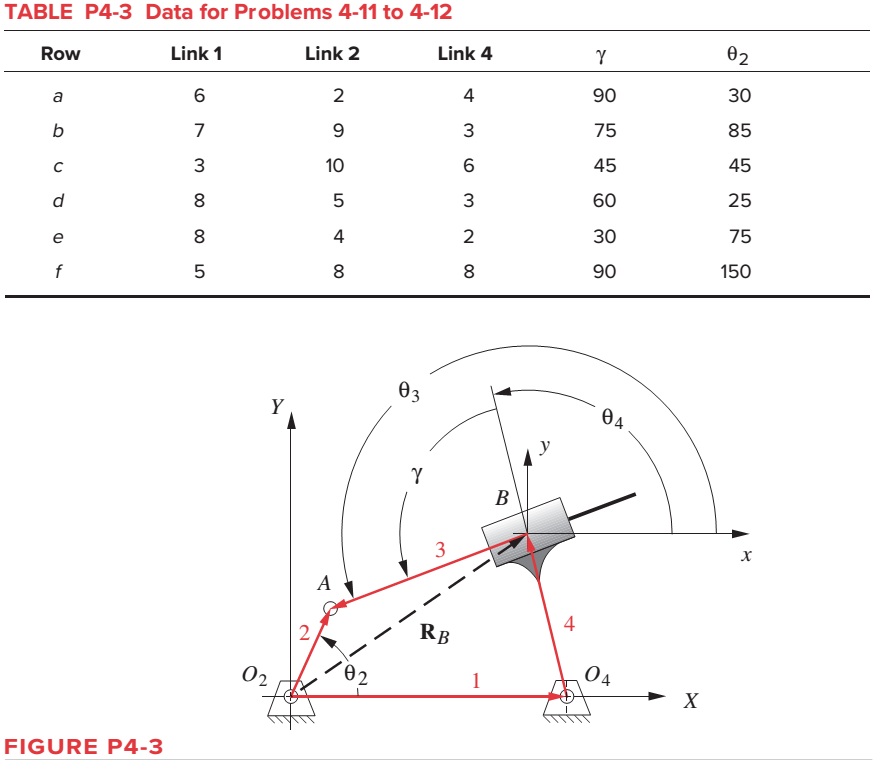
Expert Solution & Answer

Trending nowThis is a popular solution!

Students have asked these similar questions
4
Problem 2
The linkage in Figure P7-5b has O,A = O2A = 0.75, AB= 1.5, and AC = 1.2
in. The effective crank angle in the position shown is 77° and angle BAC =
30°. Find a3, A4, AB,Ac for the position shown for @2 = 15 rad/sec and a2 =
10 rad/sec in the directions shown using an analytical method.
(Hint: Create an effective linkage for the position shown and analyze it as a
pin-jointed fourbar.)the linkage has a parallelogram form
Assume rolling contact
C
@2
A
3
В
a2
2
4
04
Re-work Problem 4 on Homework 2 using Lagrange's equations (see Figure 4 below). As
indicated in the original problem statement, find the equations of motion and the constraint force
(Hint: to find the constraint force, introduce an additional generalized coordinate and associated
Lagrange multiplier).
Chapter 4 Solutions
DESIGN OF MACHINERY (LL) >C<
Ch. 4 - A position vector is defined as having a length...Ch. 4 - A particle is traveling along an arc of 6.5-in...Ch. 4 - Repeat problem 4-2 considering points A and B to...Ch. 4 - Repeat Problem 4-2 with the particles path defined...Ch. 4 - Repeat Problem 4-3 with the path of the particle...Ch. 4 - The link lengths and the value of 2 for some...Ch. 4 - Repeat Problem 4-6 except solve by the vector loop...Ch. 4 - Expand equation 4.7b and prove that it reduces to...Ch. 4 - The link lengths and the value of 2 and offset for...Ch. 4 - Repeat Problem 4-9 except solve by the vector loop...
Ch. 4 - The link lengths and the value of 2 and for some...Ch. 4 - Repeat Problem 4-11 except solve by the vector...Ch. 4 - Find the transmission angles of the linkages in...Ch. 4 - Find the minimum and maximum values of the...Ch. 4 - Find the input angles corresponding to the toggle...Ch. 4 - The link lengths. gear ratio (). phase angle (),...Ch. 4 - Repeat Problem 4-16 except solve by the vector...Ch. 4 - Figure P4-5 shows the mechanisms for the following...Ch. 4 - For one revolution of driving link 2 of the...Ch. 4 - Figure P4-7 shows a power hacksaw, used to cut...Ch. 4 - For the linkage in Figure P4-8, find its limit...Ch. 4 - For the walking-beam mechanism of Figure P4-9,...Ch. 4 - For the linkage in Figure P4-10, calculate and...Ch. 4 - For the linkage in Figure P4-11, calculate and...Ch. 4 - For the linkage in Figure P4-12, find its limit...Ch. 4 - Prob. 4.26PCh. 4 - For the linkage in Figure P4-13, find its limit...Ch. 4 - Prob. 4.28PCh. 4 - For the linkage in Figure P4-15, find its limit...Ch. 4 - For the linkage in Figure P4-15, find its limit...Ch. 4 - Prob. 4.31PCh. 4 - Prob. 4.32PCh. 4 - Figure 4-22 plots the cubic function from equation...Ch. 4 - Write a computer program or use an equation solver...Ch. 4 - Prob. 4.35PCh. 4 - Prob. 4.36PCh. 4 - Write a computer program or use an equation solver...Ch. 4 - Write a computer program or use an equation solver...Ch. 4 - Prob. 4.39PCh. 4 - Prob. 4.40PCh. 4 - Write a computer program or use an equation solver...Ch. 4 - Prob. 4.42PCh. 4 - Prob. 4.43PCh. 4 - Prob. 4.44PCh. 4 - Model the linkage shown in Figure 3-37a in...Ch. 4 - Prob. 4.46PCh. 4 - Prob. 4.47PCh. 4 - Prob. 4.48PCh. 4 - Prob. 4.49PCh. 4 - Prob. 4.50PCh. 4 - Figure 3-29g shows Evans approximate straight-line...Ch. 4 - For the linkage in Figure P4-16, what are the...Ch. 4 - The coordinates of the point P1 on link 4 in...Ch. 4 - Write a computer program or use an equation solver...Ch. 4 - For the linkage in Figure P4-17, calculate the...Ch. 4 - Prob. 4.56PCh. 4 - Prob. 4.57PCh. 4 - The elliptical trammel in Figure P4-18 must be...Ch. 4 - Prob. 4.59PCh. 4 - Prob. 4.60PCh. 4 - Repeat Problem 4-60 except solve by the vector...Ch. 4 - Write a computer program or use an equation solver...Ch. 4 - Write a computer program or use an equation solver...Ch. 4 - Write a computer program or use an equation solver...Ch. 4 - Write a computer program or use an equation solver...Ch. 4 - Figure P4-20 shows a cut-away view of a mechanism...Ch. 4 - For the linkage in Figure 3-32a, calculate and...
Additional Engineering Textbook Solutions
Find more solutions based on key concepts
What is the importance of modeling in engineering? How are the mathematical models for engineering processes pr...
Heat and Mass Transfer: Fundamentals and Applications
What is the weight in newtons of an object that has a mass of (a) 8 kg, (b) 0.04 kg, (c) 760 Mg?
Statics and Mechanics of Materials (5th Edition)
A biological fluid moves at a flow rate of m=0.02kg/s through a coiled, thin-walled, 5-mm-diameter tube submerg...
Fundamentals of Heat and Mass Transfer
CONCEPT QUESTIONS
15.CQ3 The ball rolls without slipping on the fixed surface as shown. What is the direction ...
Vector Mechanics for Engineers: Statics and Dynamics
Convert the following quantities from English to SI units: a. 98 Btu/(hr-ft-F) b. 0.24 Btu/(lbm-F) C. 0.04 Ibm/...
Heating Ventilating and Air Conditioning: Analysis and Design
A nozzle at A discharges water with an initial velocity of 36 ft/s at an angle with the horizontal. Determine ...
Vector Mechanics for Engineers: Dynamics
Knowledge Booster


Learn more about
Need a deep-dive on the concept behind this application? Look no further. Learn more about this topic, mechanical-engineering and related others by exploring similar questions and additional content below.Similar questions
- do fast.arrow_forwardStrictly use graphical method and Find T2. Do not copy from chegg their all answers are wrong.If you do I'll give thumbs down.arrow_forward3-4 Design a fourbar mechanism to give the two positions shown in Figure P3-1 of coupler motion. (See Example 3-3, p. 105.) Build a model and determine the toggle positions and the minimum transmission angle from the model. Add a driver dyad. 2.409 2.656 B2 0.751 0.470 1.750 A2 B. 1.721 FIGURE P3-1arrow_forward
- The link lengths, value of theta2, and offset for some fourbar slider-crank linkages are defined inTable P4-2. The linkage configuration and terminology are shown in Figure P4-2. For row a,draw the linkage to scale and graphically find all possible solutions (both open and crossed)for angles theta3 and slider position d.arrow_forwardSolve and Draw the following:arrow_forwardPlease draw the Kinematic diagram with joints and links, then solve the problemarrow_forward
- pls veryyyy urgentarrow_forwardThe linkage in Figure P7-5b has 04A = O2A = 0.75 , AB = 1.5 , and AC = 1.2 in . The effective crank angle in the position shown is 77º and angle BAC = 30 ° . Find a3 , AA , AB , Ac for the position shown for m2 = 15 rad / sec and a2 = 10 rad / sec2 in the directions shown using an analytical method . ( Hint : Create an effective linkage for the position shown and analyze it as a pin - jointed fourbar . ) the linkage has a parallelogram form Assume rolling contact C 02 A 3 . B 02 02 Tarrow_forwardProblem 2 The linkage in Figure P7-5b has O4A = O2A = 0.75, AB = 1.5, and AC = 1.2 in. The effective crank angle in the position shown is 77° and angle BAC = 30°. Find a3, AA. AB,Ac for the position shown for w2 = 15 rad/sec and a2 = 10 rad/sec^2 in the directions shown using an analytic method. (Hint: Create an effective linkage for the position shown and analyze it as a pin-jointed fourbar.)the linkage has a parallelogram form Assume rolling contactarrow_forward
- Problem 2 The linkage in Figure P7-5b has o4A = o2A = 0.75, AB = 1.5, and AC = 1.2 in. The effective crank angle in the position shown is 77° and angle BAC = 30°. Find a3, AA, AB, Ac for the position shown for w2 = 15 rad/sec and a2 = 10 rad/sec^2 in the directions shown using an analytic method. (Hint: Create an effective linkage for the position shown and analyze it as a pin-jointed fourbar.) the linkage has a parallelogram form Assume rolling contactarrow_forwardTe problem is.in photoarrow_forward2 Task Task 1 (40%): Get the Jacobian of the three-link manipulator below. As shown in the figure, all three joints are revolute. Joint 1’s axis is not parallel to the other two. Instead, there is a twist of 90 degrees in magnitude between axes 1 and 2. Write in terms of a frame {4} located at the tip of the hand and having the same orientation as frame {3}. Derive the Jacobian in three different ways: velocity propagation from base to tip, static force propagation from tip to base, and by direct differentiation of the kinematic equations. Compare these three approaches and discuss their pros and cons. 83 62 L1 Fig. 1. A 3R nonplanar armarrow_forward
arrow_back_ios
SEE MORE QUESTIONS
arrow_forward_ios
Recommended textbooks for you
 Elements Of ElectromagneticsMechanical EngineeringISBN:9780190698614Author:Sadiku, Matthew N. O.Publisher:Oxford University Press
 Mechanics of Materials (10th Edition)Mechanical EngineeringISBN:9780134319650Author:Russell C. HibbelerPublisher:PEARSON
 Thermodynamics: An Engineering ApproachMechanical EngineeringISBN:9781259822674Author:Yunus A. Cengel Dr., Michael A. BolesPublisher:McGraw-Hill Education
 Control Systems EngineeringMechanical EngineeringISBN:9781118170519Author:Norman S. NisePublisher:WILEY
 Mechanics of Materials (MindTap Course List)Mechanical EngineeringISBN:9781337093347Author:Barry J. Goodno, James M. GerePublisher:Cengage Learning
 Engineering Mechanics: StaticsMechanical EngineeringISBN:9781118807330Author:James L. Meriam, L. G. Kraige, J. N. BoltonPublisher:WILEY
Elements Of Electromagnetics
Mechanical Engineering
ISBN:9780190698614
Author:Sadiku, Matthew N. O.
Publisher:Oxford University Press
Mechanics of Materials (10th Edition)
Mechanical Engineering
ISBN:9780134319650
Author:Russell C. Hibbeler
Publisher:PEARSON
Thermodynamics: An Engineering Approach
Mechanical Engineering
ISBN:9781259822674
Author:Yunus A. Cengel Dr., Michael A. Boles
Publisher:McGraw-Hill Education
Control Systems Engineering
Mechanical Engineering
ISBN:9781118170519
Author:Norman S. Nise
Publisher:WILEY
Mechanics of Materials (MindTap Course List)
Mechanical Engineering
ISBN:9781337093347
Author:Barry J. Goodno, James M. Gere
Publisher:Cengage Learning
Engineering Mechanics: Statics
Mechanical Engineering
ISBN:9781118807330
Author:James L. Meriam, L. G. Kraige, J. N. Bolton
Publisher:WILEY
Polymer Basics; Author: Tonya Coffey;https://www.youtube.com/watch?v=c5gFHpWvDXk;License: Standard youtube license