
Videos
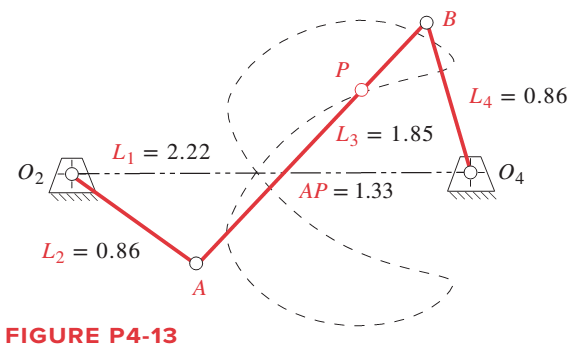
For the linkage in Figure P4-13, find its limit (toggle) positions in terms of the angle of link
Want to see the full answer?
Check out a sample textbook solution
Chapter 4 Solutions
DESIGN OF MACHINERY (LL) >C<


- PROBLEM STATEMENT: Draw the 3D version of the given figure below using Solidworks. At that instant shown below, Q₂F 15 inch, Q4B = 14 inch, Q4D = 6 inch, Q4E = 15 inch, Q2 Q4 15 inch. The crank Q4D is rotating uniformly counterclockwise at 150 rpm. Find the absolute instantaneous linear velocity in fps of point F and E and the absolute instantaneous angular velocity in rpm of the variable length crank Q₂F using your chosen method (1, 2 and 3) and Method 4. Variable: Ꮎ 6 0 Q2 5 B 30 F Q4 3 PE - 1arrow_forwardA general fourbar linkage configuration and its notation are shown in Figure below. The link lengths, coupler point location, and the values of 02 and w2 for the same fourbar linkages as used for position analysis in Chapter 4 are redefined in Table below. For the row c, draw the linkage to scale and Using an analytical method calculate w3 and w4 and find the velocity of point P. find the velocities of the pin joints A and. RPA AY 2 04 02 04 FIGURE P6-1 Configuration and terminology for the pin-Jointed fourbar linkage of Problems 6-4 to 6-5 TABLE P6-1 Data for Problems 6-4 to 6-5† Row Link 1 Link 2 Link 3 Link 4 02 02 Rpa 83 6. 2 7 30 10 6. 30 b. 9 3 8 85 -12 9. 25 10 6. 8 45 -15 10 80 O73arrow_forwardA general fourbar linkage configuration and its notation are shown in Figure below. The link lengths, coupler point location, and the values of 02 and w2 for the same fourbar linkages as used for position analysis in Chapter 4 are redefined in Table below. For the row c, draw the linkage to scale and Using an analytical method calculate w3 and w4 and find the velocity of point P. find the velocities of the pin joints A and. RPA Y B 4 03 04 02 1 02 FIGURE P6-1 Configuration and terminology for the pin-jointed fourbar linkage of Problems 6-4 to 6-5 TABLE P6-1 Data for Problems 6-4 to 6-5† Row Link 1 Link 2 Link 3 Link 4 02 Rpa 83 02 a 2 7 9. 30 10 30 7 9. 8 85 -12 9 25 3 10 8 45 -15 10 80arrow_forward
- The linkage in Figure P7-5b has 04A = O2A = 0.75 , AB = 1.5 , and AC = 1.2 in . The effective crank angle in the position shown is 77º and angle BAC = 30 ° . Find a3 , AA , AB , Ac for the position shown for m2 = 15 rad / sec and a2 = 10 rad / sec2 in the directions shown using an analytical method . ( Hint : Create an effective linkage for the position shown and analyze it as a pin - jointed fourbar . ) the linkage has a parallelogram form Assume rolling contact C 02 A 3 . B 02 02 Tarrow_forwardInput crank AB of the mechanism described above is currently at 60 degrees and is rotating CCW with a speed of 2 rad/sec, while accelerating with 2 rad/sec2.What is the tangential component of acceleration of point C with respect to B and its direction?arrow_forwardFor the Figure shown, draw the kinematic diagram and Using instantaneous center method locate all the instant centers of the mechanism.arrow_forward
- Use rotation about the current frame to calculate the transformation matrix for a rotation of 90° about yo axis and then 90° about zo axis.arrow_forwardRefer to the figure below for the mechanism. If link 2 rotates at a speed of 60 revolutions per minute in a counterclockwise direction , find the velocity, using resolution and composition method of: A point connecting link 2 to link 3 A point at the center of link 2 A point at the center of link 3 Of the slider Also, locate all the instantaneous centers.arrow_forwardThe general linkage configuration and terminology for an offset fourbar slider-crank linkage are shown in Figure below. The link lengths and the values of 02 and w2 are defined in. For the row(s) b and c, find the velocities of the pin joints A and B and the velocity of slip at the sliding joint using an analytical method. Draw the linkage to scale and label it before setting up the equations. y A 03 B Y 4 Link 3 A W2 Offset 02 04 = 90° Link 2 X 02 Slider position d TABLE P6-2 Data for Problems 6-6 to 6-7† Row Link 2 Link 3 Offset 02 02 a 1.4 4 1 45 10 2 -3 60 -12 3 8 2 -30 -15arrow_forward
- Hi I was wondering I could get help with this question. The linkage in Figure has link 1 at –36° in the global XY coordinate system.Find and plot ω4, VA, and VB inthe local coordinate system for the maximum range of motion that this linkage allows ifω2 = 20 rad/sec CCW.arrow_forwardtheta O = 55 The link length and value of O2 for some four bar linkage are defined below, (drive link =4.2 cm , coupler link =5.9 cm , follower link = 5.9 cm, fixed link= 6.85 cm 1. draw the linkage to scale and graphically find all possible solution (both open and cross) for 03 and O4 2. If w = 2 rad /s (CCW) find the angular velocity for bar 3 and 4 3.if a= 5 rad/s? (Ccw) find the normal and tangential acceleration for link 3 and 4arrow_forwardEvaluate the 3-DOF wrist as shown in Figure 2, use the conventional method to determine 1. Linear velocity and 2. Angular velocity NOTE: for JOINT 3 ( 03 ) only Connected to robot Figure 2: Wrist assembly The known position and orientation of the end of the arm point is. [-C,S2C3 + S1S3 C;S2S3 +S1C3 |-S;S2C3 – C,S3 S,S2S3 + C,C3 -C2S3 C,C2 S,C2 S2 °T3=°T;'T2?T3= C2C3 [G 0 S, 0 S, 0 -G 0 °T 1 0 0 1 -S2 0 C, 0° C2 0 S, 0 'T2 1 1 [C3 -S3 0 07 S3 C3 0 0 2T3= 1 0 0 0 1 00010 IIarrow_forward
 Elements Of ElectromagneticsMechanical EngineeringISBN:9780190698614Author:Sadiku, Matthew N. O.Publisher:Oxford University Press
 Mechanics of Materials (10th Edition)Mechanical EngineeringISBN:9780134319650Author:Russell C. HibbelerPublisher:PEARSON
 Thermodynamics: An Engineering ApproachMechanical EngineeringISBN:9781259822674Author:Yunus A. Cengel Dr., Michael A. BolesPublisher:McGraw-Hill Education
 Control Systems EngineeringMechanical EngineeringISBN:9781118170519Author:Norman S. NisePublisher:WILEY
 Mechanics of Materials (MindTap Course List)Mechanical EngineeringISBN:9781337093347Author:Barry J. Goodno, James M. GerePublisher:Cengage Learning
 Engineering Mechanics: StaticsMechanical EngineeringISBN:9781118807330Author:James L. Meriam, L. G. Kraige, J. N. BoltonPublisher:WILEY