
Shigley's Mechanical Engineering Design (McGraw-Hill Series in Mechanical Engineering)
10th Edition
ISBN: 9780073398204
Author: Richard G Budynas, Keith J Nisbett
Publisher: McGraw-Hill Education
expand_more
expand_more
format_list_bulleted
Videos
Textbook Question
Chapter 4, Problem 41P
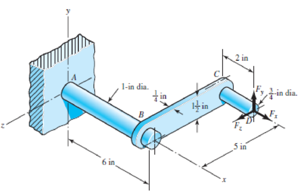
The cantilevered handle in the figure is made from mild steel that has been welded at the joints. For Fy = 200 lbf, Fx = Fz = 0, determine the vertical deflection (along the y axis) at the tip. Use superposition. See the discussion on p. 116 for the twist in the rectangular cross section in section BC.
Problem 4–41
Expert Solution & Answer
Want to see the full answer?
Check out a sample textbook solution
Chapter 4 Solutions
Shigley's Mechanical Engineering Design (McGraw-Hill Series in Mechanical Engineering)
Ch. 4 - The figure shows a torsion bar OA fixed at O,...Ch. 4 - For Prob. 41, if the simple support at point A...Ch. 4 - A torsion-bar spring consists of a prismatic bar,...Ch. 4 - An engineer is forced by geometric considerations...Ch. 4 - A bar in tension has a circular cross section and...Ch. 4 - Prob. 6PCh. 4 - Prob. 7PCh. 4 - Derive the equations given for beam 2 in Table A9...Ch. 4 - Derive the equations given for beam 5 in Table A9...Ch. 4 - The figure shows a cantilever consisting of steel...
Ch. 4 - A simply supported beam loaded by two forces is...Ch. 4 - Using superposition, find the deflection of the...Ch. 4 - A rectangular steel bar supports the two...Ch. 4 - An aluminum tube with outside diameter of 2 in and...Ch. 4 - The cantilever shown in the figure consists of two...Ch. 4 - Using superposition for the bar shown, determine...Ch. 4 - A simply supported beam has a concentrated moment...Ch. 4 - Prob. 18PCh. 4 - Using the results of Prob. 418, use superposition...Ch. 4 - Prob. 20PCh. 4 - Consider the uniformly loaded simply supported...Ch. 4 - Prob. 22PCh. 4 - Prob. 23PCh. 4 - Prob. 24PCh. 4 - Prob. 25PCh. 4 - Prob. 26PCh. 4 - Prob. 27PCh. 4 - Prob. 28PCh. 4 - 429 to 434 For the steel countershaft specified in...Ch. 4 - Prob. 30PCh. 4 - Prob. 31PCh. 4 - Prob. 32PCh. 4 - For the steel countershaft specified in the table,...Ch. 4 - For the steel countershaft specified in the table,...Ch. 4 - Prob. 35PCh. 4 - Prob. 36PCh. 4 - Prob. 37PCh. 4 - Prob. 38PCh. 4 - Prob. 39PCh. 4 - Prob. 40PCh. 4 - The cantilevered handle in the figure is made from...Ch. 4 - Prob. 42PCh. 4 - The cantilevered handle in Prob. 384, p. 154, is...Ch. 4 - A flat-bed trailer is to be designed with a...Ch. 4 - The designer of a shaft usually has a slope...Ch. 4 - Prob. 46PCh. 4 - If the diameter of the steel beam shown is 1.25...Ch. 4 - For the beam of Prob. 4-47, plot the magnitude of...Ch. 4 - Prob. 49PCh. 4 - 4-50 and 4-51 The figure shows a rectangular...Ch. 4 - and 451 the ground at one end and supported by a...Ch. 4 - The figure illustrates a stepped torsion-bar...Ch. 4 - Consider the simply supported beam 5 with a center...Ch. 4 - Prob. 54PCh. 4 - Prob. 55PCh. 4 - Solve Prob. 410 using singularity functions. Use...Ch. 4 - Prob. 57PCh. 4 - Prob. 58PCh. 4 - Prob. 59PCh. 4 - Solve Prob. 413 using singularity functions. Since...Ch. 4 - Prob. 61PCh. 4 - Solve Prob. 419 using singularity functions to...Ch. 4 - Using singularity functions, write the deflection...Ch. 4 - Determine the deflection equation for the...Ch. 4 - Use Castiglianos theorem to verify the maximum...Ch. 4 - Use Castiglianos theorem to verify the maximum...Ch. 4 - Solve Prob. 415 using Castiglianos theorem.Ch. 4 - Solve Prob. 452 using Castiglianos theoremCh. 4 - Determine the deflection at midspan for the beam...Ch. 4 - Using Castiglianos theorem, determine the...Ch. 4 - Solve Prob. 441 using Castiglianos theorem. Since...Ch. 4 - Solve Prob. 442 using Castiglianos theorem.Ch. 4 - The cantilevered handle in Prob. 384 is made from...Ch. 4 - Solve Prob. 450 using Castiglianos theorem.Ch. 4 - Solve Prob. 451 using Castiglianos theorem.Ch. 4 - The steel curved bar shown has a rectangular cross...Ch. 4 - Repeat Prob. 476 to find the vertical deflection...Ch. 4 - For the curved steel beam shown. F = 6.7 kips....Ch. 4 - A steel piston ring has a mean diameter of 70 mm....Ch. 4 - For the steel wire form shown, use Castiglianos...Ch. 4 - 4-81 and 4-82 The part shown is formed from a...Ch. 4 - 4-81 and 4-82 The part shown is formed from a...Ch. 4 - Repeat Prob. 481 for the vertical deflection at...Ch. 4 - Repeat Prob. 482 for the vertical deflection at...Ch. 4 - A hook is formed from a 2-mm-diameter steel wire...Ch. 4 - The figure shows a rectangular member OB, made...Ch. 4 - Prob. 87PCh. 4 - For the wire form shown, determine the deflection...Ch. 4 - Prob. 89PCh. 4 - Prob. 90PCh. 4 - Prob. 91PCh. 4 - Prob. 92PCh. 4 - Solve Prob. 492 using Castiglianos method and...Ch. 4 - An aluminum step bar is loaded as shown. (a)...Ch. 4 - The steel shaft shown in the figure is subjected...Ch. 4 - Repeat Prob. 495 with the diameters of section OA...Ch. 4 - The figure shows a 12- by 1-in rectangular steel...Ch. 4 - For the beam shown, determine the support...Ch. 4 - Solve Prob. 498 using Castiglianos theorem and...Ch. 4 - Consider beam 13 in Table A9, but with flexible...Ch. 4 - Prob. 101PCh. 4 - The steel beam ABCD shown is simply supported at C...Ch. 4 - Prob. 103PCh. 4 - A round tubular column has outside and inside...Ch. 4 - For the conditions of Prob. 4104, show that...Ch. 4 - Link 2, shown in the figure, is 25 mm wide, has...Ch. 4 - Link 3, shown schematically in the figure, acts as...Ch. 4 - The hydraulic cylinder shown in the figure has a...Ch. 4 - The figure shows a schematic drawing of a...Ch. 4 - If drawn, a figure for this problem would resemble...Ch. 4 - Design link CD of the hand-operated toggle press...Ch. 4 - Find the maximum values of the spring force and...Ch. 4 - As shown in the figure, the weight W1 strikes W2...Ch. 4 - Part a of the figure shows a weight W mounted...
Knowledge Booster


Learn more about
Need a deep-dive on the concept behind this application? Look no further. Learn more about this topic, mechanical-engineering and related others by exploring similar questions and additional content below.Similar questions
- The column shown in the figure is fixed at the base and free at the upper end. A compressive load P acts at the top of the column with an eccentricity e from the axis of the column. Beginning with the differential equation of the deflection curve, derive formulas for the maximum deflection S of the column and the maximum bending moment Mmaxin the column.arrow_forwardAround brass bar of a diameter d1= 20mm has upset ends each with a diameter d2= 26 mm (see figure). The lengths of the segments of the bar are L1= 0.3 m and L2= 0.1 m. Quarter-circular fillets are used at the shoulders of the bar, and the modulus of elasticity of the brass is E = 100 GPa. If the bar lengthens by 0.12 mm under a tensile load P, what is the maximum stress ??maxin the bar?arrow_forwardA ho 1 low st e el shaft ACB of outside diameter 50 mm and inside diameter 40 mm is held against rotation at ends A and B (see figure). Horizontal forces Pare applied at the ends of a vertical arm that is welded to the shaft at point C. Determine the allowable value of the forces P if the maximum permissible shear stress in the shaft is 45 MPa.arrow_forward
- Compare the angle of twist 1 for a thin-walled circular tube (see figure) calculated from the approximate theory for thin-walled bars with the angle of twist 2 calculated from the exact theory of torsion for circular bars, Express the ratio 12terms of the non-dimensional ratio ß = r/t. Calculate the ratio of angles of twist for ß = 5, 10, and 20. What conclusion about the accuracy of the approximate theory do you draw from these results?arrow_forwardSolve the preceding problem for a W 250 × 44.8 wide-flange shape with L = 3.5 m. q = 45 kN/m, h = 267 mm, b = 148 mm, rt = 13 mm, = 7.62 mm, d = 0.5 m, and a = 50 mm.arrow_forwardSolve the preceding problem for a box beam with dimensions h = 0.5 m, h = 0.18 m, and t = 22 mm. The yield stress of the steel is 210 MPa.arrow_forward
- A uniformly tapered aluminum-ally tube AB of circular cross section and length L is fixed against rotation at A and B, as shown in the figure. The outside diameters at the ends are dAand dA.A hollow section of lenth L/2 and constant thickness t = dA/10 is cast into the tube and extends from B half-way toward A. Torque T0is applied at L/2. (a) Find the reactive torques at the supports, TA and TB. Use numerical values as follows: dA = 2.5 in., L = 48., G = 309 × 106 psi, and T0= 40,000 in.-lb. (b) Repeat part (a) if the hollow sections has constant diameter dA.arrow_forwardA tubular aluminum bar (G = 4 × 10⁶ psi) of square cross section (see figure) with outer dimensions 2 in. × 2 in. must resist a torque T = 3000 1b-in. Calculate the minimum required wall thickness Tminif the allowable shear stress is 4500 psi and the allowable rate of twist is 0.01 rad/ft.arrow_forwardA solid circulai' aluminum bar AB is fixed at both ends and loaded by a uniformly distributed torque 150N·n/m. The bar has diameter d = 30 mm. Calculate the reactive torques at the supports and the angle of twist at midspan. Assume that G = 28 GPa.arrow_forward
- A long, thin-walled tapered tube AB with a circular cross section (see figure) is subjected to a torque T. The tube has length L and constant wall thickness t. The diameter to the median lines of the cross sections at the ends A and B are dAand dB, respectively. Derive the following formula for the angle of twist of the tube: Hint: If the angle of taper is small, you may obtain approximate results by applying the formulas for a thin-walled prismatic tube to a differential element of the tapered tube and then integrating along the axis of the tube.arrow_forwardA solid circular bar of steel (G = 1L4 × 106 psi) with length L = 30 in, and diameter d = 1.75 in, is subjected to pure torsion by torques T acting at the ends (see figure). Calculate the amount of strain energy V stored in the bar when the maximum shear stress is 4500 psi. From the strain energy, calculate the angle of twist 0 (in degrees).arrow_forwardTwo steel tubes are joined at B by four pins (dp= 11 mm), as shown in the cross section a—a in the fiaure. The outer diameters of the tubes are dAB= 41 mm and dBC= 28 mm. The wall thickness are tAB= 6.5 mm and tBC= 7.5 mm. The yield stress in tension for the steel is sy = 200 MPa and the ultimate stress in tension is ??U:= 340 MPa. The corresponding yield and ultimate values in shear for the pm are 80 MPa and 140 MPa, respectively. Finally, the yield and ultimate values in bearing R between the pins and the tubes are 260 MPa, and 450 MPa, respectively. Assume that the factors safety with respect to yield stress and ultimate stress are 3.5 and 4.5. respectively. (a) Calculate the allowable tensile force P allowconsidering tension in the tube (b) Recompute P allowfor shear in the pins.(c)Finaly, recomputed Pallowfor bearing between the pm and the tubes. Which is the tubes. Which is the controlling value value of P?arrow_forward
arrow_back_ios
SEE MORE QUESTIONS
arrow_forward_ios
Recommended textbooks for you
 Mechanics of Materials (MindTap Course List)Mechanical EngineeringISBN:9781337093347Author:Barry J. Goodno, James M. GerePublisher:Cengage Learning
Mechanics of Materials (MindTap Course List)
Mechanical Engineering
ISBN:9781337093347
Author:Barry J. Goodno, James M. Gere
Publisher:Cengage Learning
Differences between Temporary Joining and Permanent Joining.; Author: Academic Gain Tutorials;https://www.youtube.com/watch?v=PTr8QZhgXyg;License: Standard Youtube License