
Concept explainers
Videos
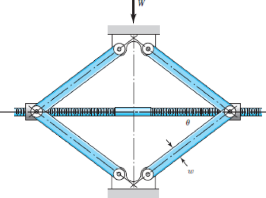
The figure shows a schematic drawing of a vehicular jack that is to be designed to support a maximum mass of 300 kg based on the use of a design factor nd = 3.50. The opposite-handed threads on the two ends of the screw are cut to allow the link angle θ to vary from 15 to 70°. The links are to be machined from AISI 1010 hot-rolled steel bars. Each of the four links is to consist of two bars, one on each side of the central bearings. The bars are to be 350 mm long and have a bar width of w = 30 mm. The pinned ends are to be designed to secure an end-condition constant of at least C = 1.4 for out-of-plane buckling. Find a suitable preferred thickness and the resulting factor of safety for this thickness.
Problem 4–109
Want to see the full answer?
Check out a sample textbook solution
Chapter 4 Solutions
Shigley's Mechanical Engineering Design (McGraw-Hill Series in Mechanical Engineering)


- A small lab scale has a rigid L-shaped frame ABC consisting of a horizontal arm AB (length b = 10 in.) and a vertical arm BC (length c = 7 in.) pivoted al point B. The pivot is attached to the outer frame BCD that stands on a laboratory bench. The position of the pointer al C is controlled by a spring, Jt = 5 lb/in., that is attached to a threaded rod. The pitch of the threads is p = 1/16 in. Under application of load W, 12 revolutions of the nut are required to bring the pointer back to the mark. Calculate the weight W.arrow_forwardThe piston in an engine is attached to a connecting rod AB, which in turn is connected to a crank arm BC (see figure). The piston slides without friction in a cylinder and is subjected to a force P (assumed to be constant) while moving to the right in the Figure. The connecting rod. with diameter d and length L, is attached at both ends by pins. The crank arm rotates about the axle at C with the pin at B moving in a circle of radius R. The axle at C, which is supported by bearings, exerts a resisting moment M against the crank arm. (a) Obtain a formula for the maximum permissible force Pallow. based upon an allowable compressive stress acin the connecting rod. (b) Calculate the Force Pallowfor the following data:arrow_forwardA small lab scale has a rigid L-shaped frame ABC consisting of a horizontal aim AB (length b = 30 cm) and a vertical arm BC (length c = 20 cm) pivoted at point B. The pivot is attached to the outer frame BCD that stands on a laboratory bench. The position of the pointer at C is controlled by two parallel springs, each having a spring constant k = 3650 N/m. that are attached to a threaded rod. The pitch of the threads is p = 1.5 mm. If the weight is 65 N. how many revolutions of the nut are required to bring the pointer back to the mark?arrow_forward
- A bicycle chain consists of a series of small links, where each are 12 mm long between the centers of the pins (see figure). You might wish to examine a bicycle chain and observe its construction. Note particularly the pins, which have a diameter of 2.5 mm. To solve this problem, make two measurements on a bicycle (see figure): (1) the length L of the crank arm from main axle to pedal axle and (2) the radius R of the sprocket (the toothed wheel, sometimes called the chainring). (a) Using your measured dimensions, calculate the tensile force T in the chain due to a force F = 800 N applied to one of the pedals. (b) Calculate the average shear stress T averin the pins.arrow_forwardRepeat Problem 3.3-1, but now use a circular tube with outer diameter d0= 2.5 in. and inner diameter di= 1.5 in.arrow_forwardCompare the angle of twist 1 for a thin-walled circular tube (see figure) calculated from the approximate theory for thin-walled bars with the angle of twist 2 calculated from the exact theory of torsion for circular bars, Express the ratio 12terms of the non-dimensional ratio ß = r/t. Calculate the ratio of angles of twist for ß = 5, 10, and 20. What conclusion about the accuracy of the approximate theory do you draw from these results?arrow_forward
- A motor driving a solid circular steel shaft with diameter d = 1.5 in, transmits 50 hp to a gear at B, The allowable shear stress in the steel is 6000 psi. Calculate the required speed of rotation (number of revolutions per minute) so that the shear stress in the shaft does not exceed the allowable limit.arrow_forwardPipe 2 has been inserted snugly into Pipe I. but the holes Tor a connecting pin do not line up; there is a gap s. The user decides to apply either force P:lo Pipe I or force P-, to Pipe 2, whichever is smaller. Determine the following using the numerical properties in the box. (a) If only P{is applied, find Pt{tips} required to close gap s; if a pin is then inserted and Ptremoved, what are reaction forces RAand RBfor this load case? (b) If only P2is applied, find P2{kips) required to close gap a; if a pin is inserted and P2removed, what are reaction forces R^ and RBfor this load case? (c) What is the maximum shear stress in the pipes, for the loads in parts (a) and (b)? (d) If a temperature increase IT is to be applied to the entire structure to close gaps{instead of applying forces Ptand P2), find the AT required to close the gap. If a pin is inserted after the gaphas closed, what are reaction forces .''.', and RBfor this case? (e) Finally, if the structure (with pin inserted) then cools to the original ambient temperature, what are reaction forces Rtand Parrow_forwardA solid circulai' aluminum bar AB is fixed at both ends and loaded by a uniformly distributed torque 150N·n/m. The bar has diameter d = 30 mm. Calculate the reactive torques at the supports and the angle of twist at midspan. Assume that G = 28 GPa.arrow_forward
- A crank arm consists of a solid segment of length bxand diameter rf, a segment of length bltand a segment of length byas shown in the figure. Two loads P act as shown: one parallel to — vand another parallel to —y. Each load P equals 1.2 kN. The crankshaft dimensions are A] = 75 mm, fr> = 125 mm, and b3= 35 mm. The diameter of the upper shaft isd = 22 mm, (a) Determine the maximum tensile, compressive, and shear stresses at point A, which is located on the surface of the shaft at the z axis. (b) Determine the maximum tensile, compressive, and shear stresses at point B, which is located on the surface of the shaft at the y axisarrow_forwardSolve Problem 11.3-3 for a W 10 × 45 steel column having a length L = 28 ft.arrow_forwardRepeat Problem 11.3-9. Use two C 150 × 12.2 steel shapes and assume that E = 205 GPa and L = 6 m.arrow_forward
 Mechanics of Materials (MindTap Course List)Mechanical EngineeringISBN:9781337093347Author:Barry J. Goodno, James M. GerePublisher:Cengage Learning