
Concept explainers
Videos
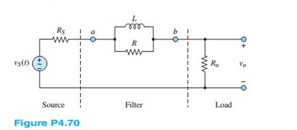
Determine the Thévenin equivalent network seen by the load
and:
a.
b.
Want to see the full answer?
Check out a sample textbook solution
Chapter 4 Solutions
Principles and Applications of Electrical Engineering


- Consider the circuit shown in Figure P4.55. a. Write the differential equation for v(t).b. Find the time constant and the form of the complementary solution.c. Usually, for an exponential forcing function like this, we would try a particular solution ofthe form vp(t) = K exp (−10t). Why doesn’t that work in this case?d. Find the particular solution. [Hint: Try a particular solution of the form vp(t)=K t exp (−10t). How ]e. Find the complete solution for v(t).arrow_forwardThe circuit shown in Figure P4.26 is operating in steady state. Determine the values of i L,v x ,and v C .arrow_forwardConsider the circuit shown in Figure P4.54. a. Write the differential equation for i(t). b. Find the time constant and the form of the complementary solution. c. Usually, for an exponential forcing function like this, we would try a particular solution of the form ip(t)=K exp (−3t). Why doesn’t that work in this case? d. Find the particular solution. [Hint: Try a particular solution of the form ip(t)=K t exp(−3t).] e. Find the complete solution for i(t).arrow_forward
- Due to components not shown in the figure, the circuit of Figure P4.41 has i L ( 0 )= I i . a. Write an expression for i L (t) for t≥0. b. Find an expression for the power delivered to the resistance as a function of time. c. Integrate the power delivered to the resistance from t=0 to t=∞, and show that the result is equal to the initial energy stored in the inductancearrow_forwardFind the transmission parameter for the network shown in Figure Q4(b).arrow_forwardAt t=0 a charged 10{μF capacitance is connected to a voltmeter, as shown in Figure P4.5. The meter can be modeled as a resistance. At t=0 the meter reads 50 V. At t=30s, the reading is 25 V. Find the resistance of the voltmeter.arrow_forward
- For the circuit shown in Figure P4.29, the switch is closed for a long time prior to t=0.Find expressions for vC(t) and sketch it to scale for −80≤t≤160 ms.arrow_forwardConsider the circuit of Figure P4.17, in which the switch instantaneously moves back and forth between contacts A and B, spending 2 seconds in each position. Thus, the capacitor repeatedly charges for 2 seconds and then discharges for 2 seconds. Assume that v C ( 0 )=0 and that the switch moves to position A at t=0. Determine v C ( 2 ), v C ( 4 ), v C ( 6 ), and v C ( 8 ).arrow_forwarda. Find the equivalent impedance ZL shown inFigure P4.66(a), as seen by the source, if thefrequency is 377 rad/s.b. If we wanted the source to see the load ascompletely resistive, what value of capacitanceshould we place between the terminals a and b asshown in Figure P4.66(b)? Hint: Find an expressionfor the equivalent impedance ZL, and then find C sothat the phase angle of the impedance is zero.arrow_forward
- The circuit shown in Figure P4.39 is operating in steady state with the switch closed prior to t=0. Find expressions for i L ( t ) for t<0 and for t≥0. Sketch iL(t) to scale versus timearrow_forwardConsider the circuit shown in Figure P4.22. What is the steady-state value of vC after the switch opens? Determine how long it takes after the switch opens before vC is within 1 percent of its steady-state value.arrow_forwardIn the circuit of Figure P4.23, the switch is in position A for a long time prior to t=0. Findexpressions for vR(t) and sketch it to scale for -2≤t≤10 s.arrow_forward
 Introductory Circuit Analysis (13th Edition)Electrical EngineeringISBN:9780133923605Author:Robert L. BoylestadPublisher:PEARSON
 Delmar's Standard Textbook Of ElectricityElectrical EngineeringISBN:9781337900348Author:Stephen L. HermanPublisher:Cengage Learning
 Programmable Logic ControllersElectrical EngineeringISBN:9780073373843Author:Frank D. PetruzellaPublisher:McGraw-Hill Education
 Fundamentals of Electric CircuitsElectrical EngineeringISBN:9780078028229Author:Charles K Alexander, Matthew SadikuPublisher:McGraw-Hill Education
 Electric Circuits. (11th Edition)Electrical EngineeringISBN:9780134746968Author:James W. Nilsson, Susan RiedelPublisher:PEARSON
 Engineering ElectromagneticsElectrical EngineeringISBN:9780078028151Author:Hayt, William H. (william Hart), Jr, BUCK, John A.Publisher:Mcgraw-hill Education,