
Concept explainers
Videos
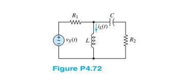
Use phasor techniques to solve for
Want to see the full answer?
Check out a sample textbook solution
Chapter 4 Solutions
Principles and Applications of Electrical Engineering


- Solve for i(t) for t>0 in the circuit of Figure P4.67, with R=200 Ω, given that i( 0+ )=0 and v C ( 0+ )=20 V [Hint: Try a particular solution of the form i p ( t )= A cos( 100t )+B sin( 100t ).]arrow_forwardi find in other explain to this that the answer is Vc+4i(x). ,,,,, but why it's not VL + Vc + 4i(x) explain the answer pleasearrow_forwardSolve for the steady-state values of i 1 , i 2 , and i 3 for the circuit shown in FigureP4.21.arrow_forward
- Subject: control Discuss the effect of adding a pole on the root locus shape , through the relative stability.arrow_forwardConsider the circuit shown in Figure P4.50. The initial current in the inductor is i s ( 0+)=0. Write the differential equation for i s(t) and solve. [Hint: Try a particular solution of the form i sp ( t )=A cos( 300t )+B sin( 300t ).]arrow_forwardDetermine expressions for and sketch v R ( t ) to scale versus time for the circuit of Figure P4.43. The circuit is operating in steady state with the switch closed prior to t=0. Consider the time interval −1≤t≤5 ms.arrow_forward
- Consider the circuit shown in Figure T4.4 in which the initial inductor current and capacitor voltage are both zero. a. Write the differential equation for v C (t). b. Find the particular solution. c. Is this circuit overdamped, critically damped, or underdamped? Find the form of the complementary solution. d. Find the complete solution for v C (t).arrow_forwardDue to components not shown in the figure, the circuit of Figure P4.41 has i L ( 0 )= I i . a. Write an expression for i L (t) for t≥0. b. Find an expression for the power delivered to the resistance as a function of time. c. Integrate the power delivered to the resistance from t=0 to t=∞, and show that the result is equal to the initial energy stored in the inductancearrow_forwardDesign a single circuit element containing one inductor, one capacitor and one resistor with v(t) of = vt=4+2e-3tV and it=-3e-3tA for t>0 . Also specify the value of the inductance, capacitance and the resistance of the tree elementarrow_forward
- Determine expressions for and sketch i s ( t ) to scale versus time for −0.2≤t≤1.0 s for the circuit of Figure P4.37.arrow_forwardThe voltage across an inductor plotted as a functionof time is shown in Figure P4.14. If L = 0.75 mH,determine the current through the inductor att = 15 μs.arrow_forwardFind the transmission parameter for the network shown in Figure Q4(b).arrow_forward
 Introductory Circuit Analysis (13th Edition)Electrical EngineeringISBN:9780133923605Author:Robert L. BoylestadPublisher:PEARSON
 Delmar's Standard Textbook Of ElectricityElectrical EngineeringISBN:9781337900348Author:Stephen L. HermanPublisher:Cengage Learning
 Programmable Logic ControllersElectrical EngineeringISBN:9780073373843Author:Frank D. PetruzellaPublisher:McGraw-Hill Education
 Fundamentals of Electric CircuitsElectrical EngineeringISBN:9780078028229Author:Charles K Alexander, Matthew SadikuPublisher:McGraw-Hill Education
 Electric Circuits. (11th Edition)Electrical EngineeringISBN:9780134746968Author:James W. Nilsson, Susan RiedelPublisher:PEARSON
 Engineering ElectromagneticsElectrical EngineeringISBN:9780078028151Author:Hayt, William H. (william Hart), Jr, BUCK, John A.Publisher:Mcgraw-hill Education,