
Concept explainers
Videos
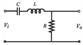
A bandpass filter passes signals with frequencies that are within a certain
where
Want to see the full answer?
Check out a sample textbook solution
Chapter 5 Solutions
EBK MATLAB: AN INTRODUCTION WITH APPLIC


- Vin OO O 0.81 A low-pass filter is built using the circuit shown. Here, R = 250 ohm, L = 5 x 10⁻⁵ H, and C = 2.5 x 10⁻⁶ F and the circuit operates at f = 100 Hz. What is the ratio Vout/Vin? 0.056 0.65 R 0.93 C L -0000 outarrow_forwardFor the given circuit below R =4.7kohm , L = 22 mH C =33nF Determine: a) Determine the upper cutoff frequency and the lower cutoff frequency in kHz. b) Determine the center frequency in kHz c) Does this circuit function as a band-pass or a band-stop filter?arrow_forwardThe below 4 figures are the angle of the transfer function of passive filters. Phase (deg) -45- Phase (deg) (Cep) sid 45 10 10 Frequency (radisec) 10² Frequency (rad/sec) Figure-1 shows the frequency response of Figure-2 shows the frequency response of Figure-3 shows the frequency response of Figure-4 shows the frequency response of 4) ( + 4 10 10" 10arrow_forward
- Compute the values of L and C to give a bandpass filter with a center frequency of 2 kHz and a bandwidth of 500 Hz. Use a 250 Ohm resistor. O a. L=17.6 mH and C= 1.27μF b. L=4.97 mH and C= 1.27μ OC.L=1.76 mH and C= 2.27μF O d. L=1.56 mH and C= 5.27μFarrow_forwardA low-pass filter consists of a 114 μF capacitor in series with a 158 resistor. The circuit is driven by an AC source with a peak voltage of 4.60 V. ▼ What is Vc when f = fc? Express your answer with the appropriate units. Vc = Submit Part C Vc = Submit What is Vc when f = fc? Express your answer with the appropriate units. ▾ Part D Value Vc = Request Answer Submit μÅ Value Request Answer What is Vc when f = 2fc? Express your answer with the appropriate units. HÅ Units Value Request Answer Units Units P ? ? ?arrow_forwardQ3/ In the High Pass Filter circuit , when the frequency increases, the voltage is increased a-decrease b-are increasing Q4/If the value of C=5nf in the High Pass Filter circuit , what is the value of R if the output is as shown in The picture F(Khz) 0.5 1 8 10 12 14 Vo(v) 0.8 1.4 3.6 4.6 5.2 5.4 5.6 5.6arrow_forward
- 18. Identify each band-pass filter configuration in . R1 C3 C2 1.0 kN 0.022 μF R4 R6 0.047 µF 0.047 µF 1.0 kf. R3 560 N R2 1.0 kfl o V out 1.0 kN C4 0.022 μF R7 560 N 1.0 kN R$ (a) 1.0 kfNarrow_forwardPart 1: According to the following schematic diagram of a series RLC Filter, you were requested to answer the following questions knowing that the value of ß is the final number of your ID: (Example: if the final # of your ID=5, the value of R1= 40+50=902) R1 L1 (40+10B)Q 5mH C1 + 50Vrms Vs = 5.066µF 500 Hz Figure 6 A. Find the equivalent impedance seen by the source B. The current passing through the circuit and determine if it is lagging or leading. C. Evaluate the phase angle D. Draw the phasor diagram for the input voltage and current.arrow_forwardL R C eer E I The series RLC circuit shown above is given as R=30N, L=25mH, C=2uF and E=9V. What is the lower cutoff frequency of the filter in Hz? 617.5 550 650 O 720.5arrow_forward
- Part A A low-pass filter with a passband gain of 5 dB and a cutoff frequency of 10 kHz is shown in (Figure 1). If the capacitor has a capacitance of 70 nF, what are R1 and R2? Express your answers in ohms to three significant figures separated by a comma. Figure 1 of 1 Vol AEo It vec R1, R2 = Ω R2 Submit Request Answer R1 Provide Feedback Voarrow_forwardQuestion: What is the bandwidth BW of the filter below? R₁ = 100 Q, R₂ = 150 Q, C₁ = 1.0 µF, and C₂ = 100 nF. Vs BW = Hz C₁ R₁ M m R₂ C₂ Voutarrow_forwardA parallel resonant band-pass filter consists of a 90 resistor in series with a parallel network made up of a 60 mH coil and a 0.02 F capacitor. The output is taken across the capacitor/coil. The coil winding has a resistance of 20. What is the center frequency of the filter? 4.59 5.59 6.89 7.59 8.59arrow_forward
 Introductory Circuit Analysis (13th Edition)Electrical EngineeringISBN:9780133923605Author:Robert L. BoylestadPublisher:PEARSON
 Delmar's Standard Textbook Of ElectricityElectrical EngineeringISBN:9781337900348Author:Stephen L. HermanPublisher:Cengage Learning
 Programmable Logic ControllersElectrical EngineeringISBN:9780073373843Author:Frank D. PetruzellaPublisher:McGraw-Hill Education
 Fundamentals of Electric CircuitsElectrical EngineeringISBN:9780078028229Author:Charles K Alexander, Matthew SadikuPublisher:McGraw-Hill Education
 Electric Circuits. (11th Edition)Electrical EngineeringISBN:9780134746968Author:James W. Nilsson, Susan RiedelPublisher:PEARSON
 Engineering ElectromagneticsElectrical EngineeringISBN:9780078028151Author:Hayt, William H. (william Hart), Jr, BUCK, John A.Publisher:Mcgraw-hill Education,